
Operation Manual


20
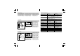
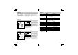
Operation/Maintenance
The Sensor Switch is
suitable for automatic
switching of light. The unit
is not suitable for special
burglary alarm systems,
since it lacks the sabotage
protection prescribed for
this purpose. The surface
should be cleaned if dirty
with a damp cloth (without
cleaners).
Declaration of conformity
The product complies with the following directives::
Low voltage directive 73/23/EEC with amendment
EMC directive 89/336/EEC with amendment
HF 360 AP:
R & TTE guideline 1999/5/EC with amendments concerning radio units and
telecommunication facilities
Herzebrock, May 2003
Burkhard Steffen, Management
Functional Warranty
This STEINEL product has
been manufactured with
great care, and its oper-
ation and safety have been
tested in conformity with the
current regulations. Produc-
tion is also submitted to
final random-sample testing.
STEINEL undertakes the
guarantee for perfect condi-
tion and function.
The warranty period is
36 months, starting on the
date of sale to the user. We
undertake to remedy faults
caused by material or manu-
facturing defects. This war-
ranty undertaking shall be
performed by the repair or
replacement of the defecti-
ve parts, at our own discre-
tion.
This warranty shall not
cover damage to wearing
parts or damage and faults
caused by incorrect oper-
ation or maintenance.
Further consequential da-
mage to external items is
excluded.
Claims under warranty shall
only be accepted if the prod-
uct is sent fully assembled
and well packed complete
with sales slip or invoice
(date of purchase and
dealer’s stamp) to the ap-
propriate Service Centre or
handed in to the dealer
within the first 6 months.
Repair Service:
Our Customer Service De-
partment will repair faults
not covered by warranty or
after the warranty period.
Please send the product
well packed to your nearest
Service Centre.
21
Instructions de montage
Cher client,
Nous vous remercions de la
confiance que vous avez té-
moignée à STEINEL en ache-
tant cet interrupteur à détec-
teur. Vous avez choisi un arti-
cle de très grande qualité, fa-
briqué, testé et conditionné
avec le plus grand soin. Avant
de l’installer, veuillez lire
atten-tivement ces instructions
de montage. En effet, seule
une installation et une mise en
ser-vice correctement
effectuées garantissent
durablement un
fonctionnement impeccable
et fiable.
Nous souhaitons que votre
nouveau interrupteur à dé-
tecteur vous apporte entière
satisfaction.
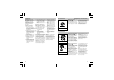
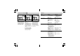
Description de l’appareil
IR 180 AP:
a
Boîtier à pose en saillie
b
Mécanisme
c
Détecteur
d
Enjoliveur
e
Poussoir pour éclairage
permanent et arrêt
permanent
f
Témoin d’éclairage
permanent et d’arrêt
permanent (DEL rouge
derrière la lentille)
g
Réglage de crépuscularité
2 - 2 000 lux
h
Temporisation
10 s - 30 min
HF 360 AP:
a
Boîtier à pose en saillie
b
Mécanisme
c
Détecteur
d
Enjoliveur
e
Poussoir pour éclairage
permanent et arrêt
permanent
f
Témoin d’éclairage
permanent et d’arrêt
permanent (DEL rouge)
g
Réglage de crépuscularité
2 - 2 000 lux
h
Temporisation
10 s - 30 min
i
Réglage de la portée
1 - 8 m
W
Avant toute intervention sur
l’interrupteur à détecteur,
couper l’alimentation élec-
trique!
W
Pendant le montage, les
conducteurs à raccorder
doivent être hors tension.
Il faut donc d’abord couper
le courant et s’assurer de
l’absence de courant à
l’aide d’un testeur de
tension.
W
L’installation de l’interrup-
teur à détecteur implique
une intervention sur le
réseau électrique et doit
donc être effectuée correc-
tement et conformément à
la norme NF C-15100.
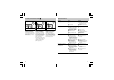
Consignes de sécurité
F