
User Manual


Appendix
UR824 Operation Manual 33
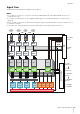
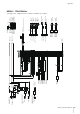
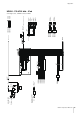
Signal Flow
The following chart indicates the signal flow in the device.
NOTE
•The controllers on the device, such as the HI-Z switch, INPUT GAIN knob, and OUTPUT LEVEL knob, are not
included in this chart.
•To configure each parameter, use the “dspMixFx UR824” (page 9) or “Dedicated Windows for Cubase Series”
(page 15).
• Please note that you cannot use the built-in Channel Strip (Ch. Strip) and Guitar Amp Classics when the sample rate is set
to 176.4 kHz or 192 kHz.
•Some parts of the following signal flow may differ depending on the routing settings in the device.
Effect
(MON.FX)
Effect
(INS.FX)
*1
Effect
(MON.FX)
Effect
(INS.FX)
Effect
(MON.FX)
Effect
(INS.FX)
Effect
(MON.FX)
Effect
(INS.FX)
*2
From
MIC/LINE/
HI-Z 1
To DAW
input
From DAW
output
To LINE
OUTPUT 1/2
To LINE
OUTPUT 7/8
To OPTICAL A
OUT 1/2
To OPTICAL B
OUT 7/8
To PHONES 1
To PHONES 2
From
MIC/LINE
HI-Z 2
From
OPTICAL
A IN 1
From
OPTICAL
B IN 8
OUTPUT SELECT
REV-X select
Volume
Pan
Volume
Pan
Volume
Pan
Volume
Pan
REV-X
Send
Level
REV-X
Send
Level
REV-X
Send
Level
REV-X
Send
Level
Volume
Pan
MIX 4
MIX 3
MIX 2
MIX 1
*3
REV-X
Return
Level
REV-X
Return
Level
REV-X
Return
Level
REV-X
Return
Level
REV-X
LOOPBACK
OFF/ON
USB