
User manual

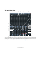
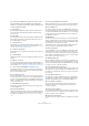
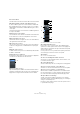
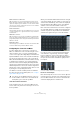
Table Of Contents
- Table of Contents
- Part I: Getting into the details
- About this manual
- Setting up your system
- VST Connections
- The Project window
- Working with projects
- Creating new projects
- Opening projects
- Closing projects
- Saving projects
- The Archive and Backup functions
- Startup Options
- The Project Setup dialog
- Zoom and view options
- Audio handling
- Auditioning audio parts and events
- Scrubbing audio
- Editing parts and events
- Range editing
- Region operations
- The Edit History dialog
- The Preferences dialog
- Working with tracks and lanes
- Playback and the Transport panel
- Recording
- Quantizing MIDI and audio
- Fades, crossfades and envelopes
- The arranger track
- The transpose functions
- Using markers
- The Mixer
- Control Room (Cubase only)
- Audio effects
- VST instruments and instrument tracks
- Surround sound (Cubase only)
- Automation
- Audio processing and functions
- The Sample Editor
- The Audio Part Editor
- The Pool
- The MediaBay
- Introduction
- Working with the MediaBay
- The Define Locations section
- The Locations section
- The Results list
- Previewing files
- The Filters section
- The Attribute Inspector
- The Loop Browser, Sound Browser, and Mini Browser windows
- Preferences
- Key commands
- Working with MediaBay-related windows
- Working with Volume databases
- Working with track presets
- Track Quick Controls
- Remote controlling Cubase
- MIDI realtime parameters and effects
- Using MIDI devices
- MIDI processing
- The MIDI editors
- Introduction
- Opening a MIDI editor
- The Key Editor – Overview
- Key Editor operations
- The In-Place Editor
- The Drum Editor – Overview
- Drum Editor operations
- Working with drum maps
- Using drum name lists
- The List Editor – Overview
- List Editor operations
- Working with SysEx messages
- Recording SysEx parameter changes
- Editing SysEx messages
- The basic Score Editor – Overview
- Score Editor operations
- Expression maps (Cubase only)
- Note Expression (Cubase only)
- The Logical Editor, Transformer, and Input Transformer
- The Project Logical Editor (Cubase only)
- Editing tempo and signature
- The Project Browser (Cubase only)
- Export Audio Mixdown
- Synchronization
- Video
- ReWire
- File handling
- Customizing
- Key commands
- Part II: Score layout and printing (Cubase only)
- How the Score Editor works
- The basics
- About this chapter
- Preparations
- Opening the Score Editor
- The project cursor
- Playing back and recording
- Page Mode
- Changing the zoom factor
- The active staff
- Making page setup settings
- Designing your work space
- About the Score Editor context menus
- About dialogs in the Score Editor
- Setting clef, key, and time signature
- Transposing instruments
- Printing from the Score Editor
- Exporting pages as image files
- Working order
- Force update
- Transcribing MIDI recordings
- Entering and editing notes
- About this chapter
- Score settings
- Note values and positions
- Adding and editing notes
- Selecting notes
- Moving notes
- Duplicating notes
- Cut, copy, and paste
- Editing pitches of individual notes
- Changing the length of notes
- Splitting a note in two
- Working with the Display Quantize tool
- Split (piano) staves
- Strategies: Multiple staves
- Inserting and editing clefs, keys, or time signatures
- Deleting notes
- Staff settings
- Polyphonic voicing
- About this chapter
- Background: Polyphonic voicing
- Setting up the voices
- Strategies: How many voices do I need?
- Entering notes into voices
- Checking which voice a note belongs to
- Moving notes between voices
- Handling rests
- Voices and Display Quantize
- Creating crossed voicings
- Automatic polyphonic voicing – Merge All Staves
- Converting voices to tracks – Extract Voices
- Additional note and rest formatting
- Working with symbols
- Working with chords
- Working with text
- Working with layouts
- Working with MusicXML
- Designing your score: additional techniques
- Scoring for drums
- Creating tablature
- The score and MIDI playback
- Tips and Tricks
- Index
178
Control Room (Cubase only)
The Control Room Mixer has a variety of controls, some
that are similar to the Project Mixer and some that are
unique to Control Room operations. In the following each
control is briefly described:
1. Input Phase
Each external input and Monitor speaker output has an Input Phase re-
versal switch. When lit, all audio paths within the channel have their
phase reversed.
2. Input Gain
Each external input, Monitor speaker output and the Talkback input has
an Input Gain control. When an external input or Monitor becomes ac
-
tive, the Gain settings are recalled.
3. Channel inserts
Each channel in the Control Room Mixer has inserts available. For de-
tailed information about inserts in the Control Room Mixer, see “Config-
uring the Control Room Mixer” on page 180.
4. Channel configuration
This displays the current configuration of audio paths in the channel, e. g.
Stereo or 5.1.
5. Channel labels
This displays the name of the channel as defined in the VST Connections
window.
6. Expansion controls
There are several arrow buttons that open and close additional panels of
the Control Room Mixer. By default, the extended panels are hidden. For
more information, see
“Configuring the Control Room Mixer” on page 180.
7. Control Room and Headphone input selectors
These buttons allow you to select input sources for the Control Room
and Headphone channels. The choices are External Input, Monitor Mix, or
any one of the four Studio channels.
8. Use Reference Level
When you click this button, the Control Room level is set to the reference
level set in the Preferences dialog, e.
g. a level for calibrated mixing envi-
ronments such as film dubbing stages. Press [Alt]/[Option] and click this
button to set the Reference Level setting in the Preferences dialog to the
current Control Room level.
9. Show Meters/Inserts button
This allows you to switch between the display of meters and inserts for
the extended Mixer view.
10. Listen Bus AFL/PFL
This button determines whether the signal of a listen-enabled channel is
routed to the Control Room channel after applying the fader and pan set
-
tings (AFL) or before (PFL) (see “Listen mode (Cubase only)” on page
156).
11. Listen Activate/Deactivate All Listen
When lit, this indicates that one or more channels in the Project Mixer are
listen-enabled. Clicking this button deactivates Listen for all channels.
12. Listen DIM Level
This gain control adjusts the volume of the Main Mix when channels have
been put in Listen mode. This allows you to keep listen-enabled channels
in context with the Main Mix. If the Listen DIM level is set to minus infinity,
you will only hear the listen-enabled channels. Any other setting leaves
the Main Mix at a lower level.
13. DIM Signal
This turns the Control Room level down by a preset amount (the default
setting is -30
dB). This allows a quick reduction in monitor volume with-
out disturbing the current monitor level. Clicking on the DIM button again
returns the monitor level to the previous setting.
The default value can be changed by adjusting the “Main Dim Volume”
setting in the Preferences dialog (VST–Control Room page).
14. Activate Talkback
Click the TALK button to turn on the Talkback system, allowing commu-
nication between the control room and performers in the studio. There
are two modes of operation: momentary mode used by clicking and hold
-
ing the Talk button, and latch mode where clicking once turns the Talk-
back on until you click it again to turn it off.
15. Talkback DIM Level
When the Talkback is enabled, this control allows you to determine how
much the output of all the channels in the Control Room Mixer is reduced.
This prevents unwanted feedback. If the Talkback DIM level is set to 0
dB,
no change occurs in the Control Room channels.
16. Cycle Downmix Preset Selection
The Control Room allows four different speaker downmix settings for au-
ditioning with various speaker configurations. Clicking this button cycles
through the four downmix presets. Various icons appear to show which
preset is active.
17. Cycle Monitor Selection
Pressing this button changes the Monitor selection to the next available
set. As Monitors are changed, so are the downmix presets, Monitor inserts,
Input Gain, and Input Phase controls associated with that Monitor set.
18. Listen Enable for Output
This activates the Listen bus function for either the Control Room or
Headphone output. If this is not enabled, the Listen bus will not be
routed to that channel.
19. Listen Level for Output
This level adjustment determines how loud Listen bus signals are when
routed to the Control Room or Headphone output. Clicking on the num
-
ber pops up a fader control for adjustment.
20. Activate channel buttons
These buttons turn each channel’s output on or off. When lit, the channel
is on.