
User manual

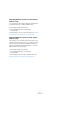

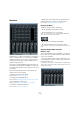
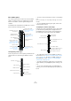
Table Of Contents
- Table of Contents
- Part I: Getting into the details
- About this manual
- Setting up your system
- VST Connections
- The Project window
- Working with projects
- Creating new projects
- Opening projects
- Closing projects
- Saving projects
- The Archive and Backup functions
- Startup Options
- The Project Setup dialog
- Zoom and view options
- Audio handling
- Auditioning audio parts and events
- Scrubbing audio
- Editing parts and events
- Range editing
- Region operations
- The Edit History dialog
- The Preferences dialog
- Working with tracks and lanes
- Playback and the Transport panel
- Recording
- Quantizing MIDI and audio
- Fades, crossfades and envelopes
- The arranger track
- The transpose functions
- Using markers
- The Mixer
- Control Room (Cubase only)
- Audio effects
- VST instruments and instrument tracks
- Surround sound (Cubase only)
- Automation
- Audio processing and functions
- The Sample Editor
- The Audio Part Editor
- The Pool
- The MediaBay
- Introduction
- Working with the MediaBay
- The Define Locations section
- The Locations section
- The Results list
- Previewing files
- The Filters section
- The Attribute Inspector
- The Loop Browser, Sound Browser, and Mini Browser windows
- Preferences
- Key commands
- Working with MediaBay-related windows
- Working with Volume databases
- Working with track presets
- Track Quick Controls
- Remote controlling Cubase
- MIDI realtime parameters and effects
- Using MIDI devices
- MIDI processing
- The MIDI editors
- Introduction
- Opening a MIDI editor
- The Key Editor – Overview
- Key Editor operations
- The In-Place Editor
- The Drum Editor – Overview
- Drum Editor operations
- Working with drum maps
- Using drum name lists
- The List Editor – Overview
- List Editor operations
- Working with SysEx messages
- Recording SysEx parameter changes
- Editing SysEx messages
- The basic Score Editor – Overview
- Score Editor operations
- Expression maps (Cubase only)
- Note Expression (Cubase only)
- The Logical Editor, Transformer, and Input Transformer
- The Project Logical Editor (Cubase only)
- Editing tempo and signature
- The Project Browser (Cubase only)
- Export Audio Mixdown
- Synchronization
- Video
- ReWire
- File handling
- Customizing
- Key commands
- Part II: Score layout and printing (Cubase only)
- How the Score Editor works
- The basics
- About this chapter
- Preparations
- Opening the Score Editor
- The project cursor
- Playing back and recording
- Page Mode
- Changing the zoom factor
- The active staff
- Making page setup settings
- Designing your work space
- About the Score Editor context menus
- About dialogs in the Score Editor
- Setting clef, key, and time signature
- Transposing instruments
- Printing from the Score Editor
- Exporting pages as image files
- Working order
- Force update
- Transcribing MIDI recordings
- Entering and editing notes
- About this chapter
- Score settings
- Note values and positions
- Adding and editing notes
- Selecting notes
- Moving notes
- Duplicating notes
- Cut, copy, and paste
- Editing pitches of individual notes
- Changing the length of notes
- Splitting a note in two
- Working with the Display Quantize tool
- Split (piano) staves
- Strategies: Multiple staves
- Inserting and editing clefs, keys, or time signatures
- Deleting notes
- Staff settings
- Polyphonic voicing
- About this chapter
- Background: Polyphonic voicing
- Setting up the voices
- Strategies: How many voices do I need?
- Entering notes into voices
- Checking which voice a note belongs to
- Moving notes between voices
- Handling rests
- Voices and Display Quantize
- Creating crossed voicings
- Automatic polyphonic voicing – Merge All Staves
- Converting voices to tracks – Extract Voices
- Additional note and rest formatting
- Working with symbols
- Working with chords
- Working with text
- Working with layouts
- Working with MusicXML
- Designing your score: additional techniques
- Scoring for drums
- Creating tablature
- The score and MIDI playback
- Tips and Tricks
- Index

147
The Mixer
• You can also save channel configurations as view sets
(see
“Channel view sets” on page 151), which are then
accessible from all Mixer windows.
Ö All options for configuring the Mixer described in this
chapter are identical for all Mixer windows.
The use of multiple Mixer windows combined with the abil-
ity to recall different Mixer configurations enables you to
focus on the task at hand and keep window scrolling
down to a minimum.
What channel types can be shown in the
Mixer?
The following track-based channel types are shown in the
Mixer:
•Audio
•MIDI
• Effect return channels (referred to as FX channels in the Proj-
ect window)
• Group channels
• Instrument track channels
The order of audio, MIDI, instrument, group, and effect
return channel strips (from left to right) in the Mixer corre-
sponds to the track list in the Project window (from top to
bottom). If you reorder tracks of these types in the track
list, this will be mirrored in the Mixer.
In addition to the above, the following channel types are
also shown in the Mixer:
• Activated ReWire channels, see the chapter “ReWire”
on page 517.
ReWire channels cannot be reordered and always appear to the right of
other channels in the main Mixer pane.
• VST instrument channels, see the chapter “VST instru-
ments and instrument tracks” on page 206.
VST instrument (VSTi) channels can be reordered in the track list which
will in turn be mirrored in the Mixer.
Input and output busses in the Mixer
The busses you set up in the VST Connections window
are represented by input and output channels in the Mixer.
They are shown in separate panes (to the left and right of
the regular channel strips), with their own dividers and
horizontal scrollbars. Input and output channel strips are
very similar. The only difference between the two is that in
-
put channels have no Solo buttons.
• You can hide and show these panes by activating or
deactivating the “Hide Input Channels” or “Hide Output
Channels” button on the common panel (see “The com-
mon panel” on page 149).
For input and output channel strips the following controls
are available:
• You can check and adjust the input level using the Input
Gain knobs and/or the level fader.
See “Setting input levels” on page 94.
• You can change the phase of the input signal.
This is done by clicking the Input Phase button next to the Input Gain
control.
Input Gain
Bus level meter
Automation controls
Clipping indicator, see
“Setting input levels”
on page 94.
Speaker configuration
Inserts and EQ
indicators/bypass
buttons
Input Phase button
Mute, Solo, and Listen
buttons (only the Output
bus features a Solo
button)
Bus volume fader
Edit button
Pan control