
User manual
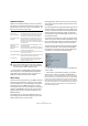

Table Of Contents
- Table of Contents
- Part I: Getting into the details
- About this manual
- VST Connections: Setting up input and output busses
- The Project window
- Playback and the Transport panel
- Recording
- Fades, crossfades and envelopes
- The Arranger track
- The Transpose functions
- The mixer
- Control Room (Cubase only)
- Audio effects
- VST Instruments and Instrument tracks
- Surround sound (Cubase only)
- Automation
- Audio processing and functions
- The Sample Editor
- The Audio Part Editor
- The Pool
- The MediaBay
- Working with Track Presets
- Track Quick Controls
- Remote controlling Cubase
- MIDI realtime parameters and effects
- Using MIDI devices
- MIDI processing and quantizing
- The MIDI editors
- Introduction
- Opening a MIDI editor
- The Key Editor - Overview
- Key Editor operations
- The In-Place Editor
- The Drum Editor - Overview
- Drum Editor operations
- Working with drum maps
- Using drum name lists
- The List Editor - Overview
- List Editor operations
- Working with System Exclusive messages
- Recording System Exclusive parameter changes
- Editing System Exclusive messages
- VST Expression
- The Logical Editor, Transformer and Input Transformer
- The Project Logical Editor
- Editing tempo and signature
- The Project Browser
- Export Audio Mixdown
- Synchronization
- Video
- ReWire
- File handling
- Customizing
- Key commands
- Part II: Score layout and printing
- How the Score Editor works
- The basics
- About this chapter
- Preparations
- Opening the Score Editor
- The project cursor
- Playing back and recording
- Page Mode
- Changing the Zoom factor
- The active staff
- Making page setup settings
- Designing your work space
- About the Score Editor context menus
- About dialogs in the Score Editor
- Setting key, clef and time signature
- Transposing instruments
- Printing from the Score Editor
- Exporting pages as image files
- Working order
- Force update
- Transcribing MIDI recordings
- Entering and editing notes
- About this chapter
- Score settings
- Note values and positions
- Adding and editing notes
- Selecting notes
- Moving notes
- Duplicating notes
- Cut, copy and paste
- Editing pitches of individual notes
- Changing the length of notes
- Splitting a note in two
- Working with the Display Quantize tool
- Split (piano) staves
- Strategies: Multiple staves
- Inserting and editing clefs, keys or time signatures
- Deleting notes
- Staff settings
- Polyphonic voicing
- About this chapter
- Background: Polyphonic voicing
- Setting up the voices
- Strategies: How many voices do I need?
- Entering notes into voices
- Checking which voice a note belongs to
- Moving notes between voices
- Handling rests
- Voices and Display Quantize
- Creating crossed voicings
- Automatic polyphonic voicing - Merge All Staves
- Converting voices to tracks - Extract Voices
- Additional note and rest formatting
- Working with symbols
- Working with chords
- Working with text
- Working with layouts
- Working with MusicXML
- Designing your score: additional techniques
- Scoring for drums
- Creating tablature
- The score and MIDI playback
- Tips and Tricks
- Index

62
Playback and the Transport panel
About the Transport panel display formats
Primary time display (left) and secondary time display (right)
The time unit shown in the ruler can be independent from
the time unit shown in the main time display on the Trans-
port panel. This means that you can display timecode in
the transport position display and bars and beats in the
ruler, for example. In addition, there is a secondary time
display to the right of the primary time display which is
also independent, giving you three different time units
shown at the same time (in the Project window, you can
also create additional ruler tracks – see “Using multiple
rulers – ruler tracks (Cubase only)” on page 33).
The following rules apply:
• If you change the time format of the primary time display
on the Transport panel, the time format of the ruler will be
changed as well.
This is the same as changing the display format in the Project Setup.
Therefore, to have different display formats in the ruler and the main time
display you should change the format in the ruler.
• The primary time display format is set on the pop-up
menu to the right in the main position display.
• This setting also determines the time format displayed
for the left and right locators on the Transport panel.
• The secondary time display is completely independent,
and the display format is set on the pop-up menu to the
right in the secondary time display.
• You can swap time formats between the primary and
secondary time displays by clicking the double arrow sym-
bol between them.
The left and right locators
The left and right locators are a pair of position markers
used for specifying punch-in and punch-out positions dur-
ing recording, and as boundaries for cycle playback and
recording.
Ö When cycle mode is activated on the Transport panel,
the area between the left and right locator will be repeated
(cycled) on playback.
However, if the right locator is positioned before the left, this will work as
a “jump” or “skip mode” – when the project cursor reaches the right lo-
cator it will immediately jump to the left locator position and continue
playback from there.
There are several ways to set locator positions:
• To set the left locator, press [Ctrl]/[Command] and click
at the desired position in the ruler.
Similarly, pressing [Alt]/[Option] and clicking in the ruler sets the right lo-
cator. You can also drag the locator “handles” directly in the ruler.
The locators are indicated by the “flags” in the ruler. The area between
the locators is highlighted in the ruler and in the Project window (see
“Appearance” on page 474). Note that if the right locator is before the
left locator, the color of the ruler between the locators will change (from
blue to red).
• Click and drag in the upper half of the ruler to “draw” a
locator range.
If you click on an existing locator range, you can drag to move it.
• Pressing [Ctrl]/[Command] and pressing [1] or [2] on
the numeric keypad sets the left or right locator to the pro-
ject cursor position.
Similarly, you can press [1] or [2] on the numeric keypad (without [Ctrl]/
[Command]) to set the project cursor position to the left or right locator
position. Note that these are default key commands – you can change
these if you like.
• By creating cycle markers you can store any number of
left and right locator positions, which can be recalled by
simply double-clicking on the corresponding marker (see
“Editing markers on the Marker track” on page 55).
• The “Locators to Selection” item on the Transport menu
(default key command [P]) sets the locators to encompass
the current selection.
This is available if you have selected one or several events or made a se-
lection range.
• You can also adjust the locators numerically on the
Transport panel.
Clicking the L/R buttons in the locator section on the Transport panel will
move the project cursor to the respective locator. If you press [Alt]/[Op-
tion] and click the L or R button, the corresponding locator will be set to
the current project cursor position.