
User manual
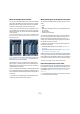
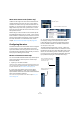

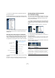
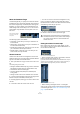
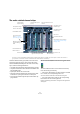
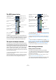
Table Of Contents
- Table of Contents
- Part I: Getting into the details
- About this manual
- VST Connections: Setting up input and output busses
- The Project window
- Playback and the Transport panel
- Recording
- Fades, crossfades and envelopes
- The Arranger track
- The Transpose functions
- The mixer
- Control Room (Cubase only)
- Audio effects
- VST Instruments and Instrument tracks
- Surround sound (Cubase only)
- Automation
- Audio processing and functions
- The Sample Editor
- The Audio Part Editor
- The Pool
- The MediaBay
- Working with Track Presets
- Track Quick Controls
- Remote controlling Cubase
- MIDI realtime parameters and effects
- Using MIDI devices
- MIDI processing and quantizing
- The MIDI editors
- Introduction
- Opening a MIDI editor
- The Key Editor - Overview
- Key Editor operations
- The In-Place Editor
- The Drum Editor - Overview
- Drum Editor operations
- Working with drum maps
- Using drum name lists
- The List Editor - Overview
- List Editor operations
- Working with System Exclusive messages
- Recording System Exclusive parameter changes
- Editing System Exclusive messages
- VST Expression
- The Logical Editor, Transformer and Input Transformer
- The Project Logical Editor
- Editing tempo and signature
- The Project Browser
- Export Audio Mixdown
- Synchronization
- Video
- ReWire
- File handling
- Customizing
- Key commands
- Part II: Score layout and printing
- How the Score Editor works
- The basics
- About this chapter
- Preparations
- Opening the Score Editor
- The project cursor
- Playing back and recording
- Page Mode
- Changing the Zoom factor
- The active staff
- Making page setup settings
- Designing your work space
- About the Score Editor context menus
- About dialogs in the Score Editor
- Setting key, clef and time signature
- Transposing instruments
- Printing from the Score Editor
- Exporting pages as image files
- Working order
- Force update
- Transcribing MIDI recordings
- Entering and editing notes
- About this chapter
- Score settings
- Note values and positions
- Adding and editing notes
- Selecting notes
- Moving notes
- Duplicating notes
- Cut, copy and paste
- Editing pitches of individual notes
- Changing the length of notes
- Splitting a note in two
- Working with the Display Quantize tool
- Split (piano) staves
- Strategies: Multiple staves
- Inserting and editing clefs, keys or time signatures
- Deleting notes
- Staff settings
- Polyphonic voicing
- About this chapter
- Background: Polyphonic voicing
- Setting up the voices
- Strategies: How many voices do I need?
- Entering notes into voices
- Checking which voice a note belongs to
- Moving notes between voices
- Handling rests
- Voices and Display Quantize
- Creating crossed voicings
- Automatic polyphonic voicing - Merge All Staves
- Converting voices to tracks - Extract Voices
- Additional note and rest formatting
- Working with symbols
- Working with chords
- Working with text
- Working with layouts
- Working with MusicXML
- Designing your score: additional techniques
- Scoring for drums
- Creating tablature
- The score and MIDI playback
- Tips and Tricks
- Index

118
The mixer
• MIDI channels handle fader volume changes in the mixer
by sending out MIDI volume messages to the connected in-
strument(s).
Connected instruments must be set to respond to MIDI messages (such
as MIDI volume in this case) for this to function properly.
• The fader settings are displayed numerically below the
faders, in dB for audio channels and in the MIDI volume 0
to 127 value range for MIDI channels.
You can click in the fader value fields and enter a volume setting by typing.
• To make fine volume adjustments, hold down [Shift]
when you move the faders.
• If you hold down [Ctrl]/[Command] and click on a fader,
it will be reset to its default value, i.e. 0.0dB for audio
channels, or MIDI volume 100 for MIDI channels.
This reset to default values works for most mixer parameters.
You can use the faders to set up a volume balance be-
tween the audio and MIDI channels and perform a manual
mix by moving the faders and other controls while playing
back. By using the Write function (see “Enabling and
disabling the writing of automation data” on page 189),
you can automate the levels and most mixer actions.
About the level meters for audio channels
When playing back audio in Cubase, the level meters in
the mixer show the level of each audio channel.
• Directly below the level meter is a small level readout –
this shows the highest registered level in the signal.
Click this to reset the peak levels.
• Peak levels can also be shown as static horizontal lines
in the meter, see “Changing the meter characteristics” on
page 126.
If the peak level of the audio goes above 0dB, the numer-
ical level indicator will show a positive value (i.e. a value
above 0dB).
Ö Cubase uses 32 bit floating point processing internally,
so there is virtually limitless headroom – signals can go way
beyond 0dB without clipping. Having higher levels than
0dB for individual audio channels is therefore not a problem
in itself. The audio quality will not be degraded by this.
However, when many high level signals are mixed in an output bus, this
may require that you lower the output channel level a lot (see below).
Therefore it is good practice to keep the maximum levels for individual
audio channels roughly around 0dB.
About the level meters for input and output channels
For the input and output channels, things are different. I/O
channels have clipping indicators (input channels are only
shown in Cubase).
• When you are recording, clipping can occur when the
analog signal is converted to digital in the audio hardware.
With Cubase, it is also possible to get clipping in the signal being re-
corded to disk (when 16 or 24 bit record format is used and you have
adjusted the mixer settings for the input channel). For more information,
see “Setting input levels” on page 71.
• In the output busses, the floating point audio is converted
to the resolution of the audio hardware. In the integer audio
domain, the maximum level is 0dB – higher levels will cause
the clipping indicator for each bus to light up.
If the clipping indicators light up for a bus, this indicates actual clipping –
digital distortion which should always be avoided.
!
It is also possible to create volume envelopes for
separate events in the Project window or Audio Part
Editor (see “Event Envelopes” on page 95) or to
make static volume settings for an event on the info
line or with the volume handle (see “About the vo-
lume handle” on page 90).
!
When Direct Monitoring is used and the option “Map
input bus metering to Audio track (in Direct Monitor-
ing)” is activated in the Preferences (VST–Metering
page), the level meters in the mixer will show the level
of the input bus instead.
!
If the clipping indicator lights up for an output chan-
nel, reset the indicator by clicking on it, and lower the
level until the indicator does not light up.