
User guide


RELAY 2
30 AMP
BLACK
LOAD # 1
LOAD # 2
CONTROLLED
TO
CONTROLLED
TO
BLACK
RED
RELAY 1
30 AMP
OVERRIDE
LIGHT
TRANSFORMER
DIP SWITCHES
(See Note 1)
RED
LIGHT
INDICATOR
MICROPROCESSOR
L2
L1
CONNECTIONS
LINE VOLTAGE
(See Note 3)
120 VOLT
240 120 L1
( )
OR
208/240 VOLT
277V
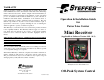
ORDER
SPECIAL
240 120 L1
L2
L1
////
(See Note 2)
2-POLE OPTION
(See Note 4)
LINE VOLTAGE WIRING AND CIRCUIT BOARD
CONFIGURATION DIAGRAM
(single pole or double pole configuration)
This Device MUST be Grounded.
Grounding and Bonding is not shown in this Diagram.
For reference to the “NOTES” listed in this diagram, refer to the Notes
section on page 8 in this manual.
DIP SWITCH SETTINGS
DIP SWITCH 1: ANTICIPATED PEAK (PRE-PEAK) OPERATION MODE
This dip switch determines how an anticipated peak (pre-peak) signal will affect
the mini receiver’ s relay(s). For power companies desiring to control loads
separately using multiple signals, this dip switch can be used to do peak control
of devices on a separate rate/control strategy.
FACTORY DEFAULT SETTING = OFF
Off = Relay(s) will not respond to an anticipated peak (pre-peak) signal.
On = Relay(s) will be activated by an anticipated peak (pre-peak) signal.
The peak signal is priority signal. When a peak signal is being
received, no other signal will be recognized.
DIP SWITCH 2, 3, 4 & 5: PLC CHANNEL SELECTION
The mini receiver can receive information on one of fifteen channels, depending
on which channel the transmitting device is set to transmit on. The mini receiver
and the transmitting device MUST be set to the same channel for proper
communication to occur.
To select the Power Line Carrier channel desired, use the chart below and set dip
switches 2, 3, 4,and 5 to the proper positions.
FACTORY DEFAULT SETTING = No PLC Channel selected (2 OFF, 3 OFF, 4
OFF, 5 OFF)
A specific channel must be selected at time of installation.
C
HANNEL DIPSWITCH 2 DIPSWITCH 3 DIPSWITCH 4 DIPSWITCH 5
0 OFF OFF OFF OFF
1 ON OFF OFF OFF
2 OFF ON OFF OFF
3 ON ON OFF OFF
4 OFF OFF ON OFF
5 ON OFF ON OFF
6 OFF ON ON OFF
7 ON ON ON OFF
8 OFF OFF OFF ON
9 ON OFF OFF ON
10 OFF ON OFF ON
11 ON ON OFF ON
12 OFF OFF ON ON
13 ON OFF ON ON
14 OFF ON ON ON
15 ON ON ON ON
6
3