
Manual
Relay 9
On
OV4
OV3
OV2
OV1
C
OVS
OVR
OVC
(See Note 3)
Water Heater ETS
Baseboard
Off
1 2 3
CIRCUIT 1
Baseboard Circuit
Typical
Typical
Circuit
Water
Heater
Relay 3 Relay 2
(See Note 1)
Override
CIRCUIT 5CIRCUIT 3CIRCUIT 2 CIRCUIT 4 CIRCUIT 7CIRCUIT 6 CIRCUIT 8 CIRCUIT 9
Relay 6
(See Note 2)
Jumper (J9)
Relay 4 Relay 5
Relay 7 Relay 8
Connect to "OS"
Connect to "OV3"
Connect to "C"
Connect to "E"
Switch
Connect to "P"
Connect to "R"
Switch Switch
Relay 1
(OPTIONAL)
SENSOR
OUTDOOR
Jumper (J8)
1 2 3
Override
Microprocessor
Transformer
OS
OS
P
R
E
A
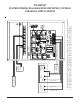
"EXAMPLE"
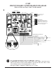
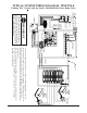
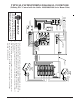
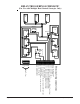
SYSTEM WIRING DIAGRAM FOR MULTIPLE CONTROL
STRATEGY APPLICATIONS
1. Dip switch 6 must be "ON" to enable independent relay control. (Refer to dip switch 6 setting description in this manual.)
2. Override Jumper J8 must be "OFF" in this application. (Refer to Note 6 in the Notes section of this manual.)
3. Override Jumper J9 must be "ON" in this application. (Refer to Note 6 in the Notes section of this manual.)
Comfort Control Relay Panel (CCRP) Page 11