
Manual
Relay 2 & 3 Override
Relay 7, 8, & 9 Override
the Relays and
OVC
OVR
OVS
OV4
OV2
OV1
OV3
Terminal Block
in the CCRP.)
Factory Installed
Wire Leads.
(This End is
Connected at
the Factory to
LOW VOLTAGE
CONNECTIONS
Relay 1 Override
Override Common
STEFFES
CONNECTIONS
LOW VOLTAGE
Override Hot
CORPORATION
Override Switch
105
Black Circuit 2
Red Circuit 2
TYPICAL SUPPLY
Black Circuit 1
Red Circuit 1
CIRCUITS
9
8
4
3
7
6
2
240VAC SOURCE
1
BLACK
GREEN
BLACK
BLUE
BLUE
FEED
OPTION
DUAL
RED
RED
RED
RED
BLUE
BLACK
BLUE
GREEN
2003 DO NOT HAVE
MODELS 2002 AND
A RED CIRCUIT.
SINGLE
OPTION
BLACK
NOTE:
FEED
A
C
E
(SEE NOTE 1)
REMOTE
OUTDOOR
(OPTIONAL)
SENSOR
Override Module
(OPTIONAL)
P
OS
OS
R
PEAK CONTROL
SWITCH
UTILITY
Only if Anticipated Peak
Set Back is Optional
Room Temperature
TO CONTROLLED LOAD
TO CONTROLLED LOAD
(30 Amp Circuit Maximum)
(20 Amp Circuit Maximum)
The Power Company.
Is Being Utilized By
(SEE NOTE 2)
SYSTEM GROUND
CIRCUIT 3 CIRCUIT 7 CIRCUIT 9CIRCUIT 8CIRCUIT 6CIRCUIT 4 CIRCUIT 5
20 AMP MAX
CIRCUIT ONE
CIRCUIT 2CIRCUIT 1
(See Note 3)
ANTICIPATED
TEMPERATURE
PEAK CONTROL
UTILITY
SWITCH
SET BACK
ROOM
Field
Installed
Wiring
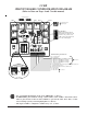
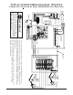
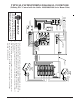
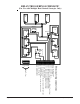
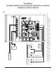
TYPICAL SYSTEM WIRING DIAGRAM - NINE POLE
(Utilizing PLC Control with the Steffes 1000/2000/2100 Series Room Units)
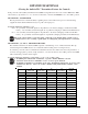
A panel label is provided in the package of
screws used to mount the front panel. Apply
this label to the service panel to identify the
breaker feeding CCRP circuit 1.
IMPORTANT
1. Loads connected between L1 and L2 on circuit 1 will be uninterrupted. Loads con-
nected between T1 and L2 on circuit 1 will be interrupted. CCRP circuit 1 feeds both
output circuit 1 and the panels internal controls. Maximum fuse size is 20 amps.
2. The system grounding and bonding must be sized and installed in compliance with all
applicable codes.
3. Any loads requiring greater than a 20 amp circuit, such as a water heater, must never
be connected to circuit 1 in the CCRP as circuit 1 is only capable of controlling a
maximum of a 20 amp circuit.
Page 8 Comfort Control Relay Panel (CCRP)