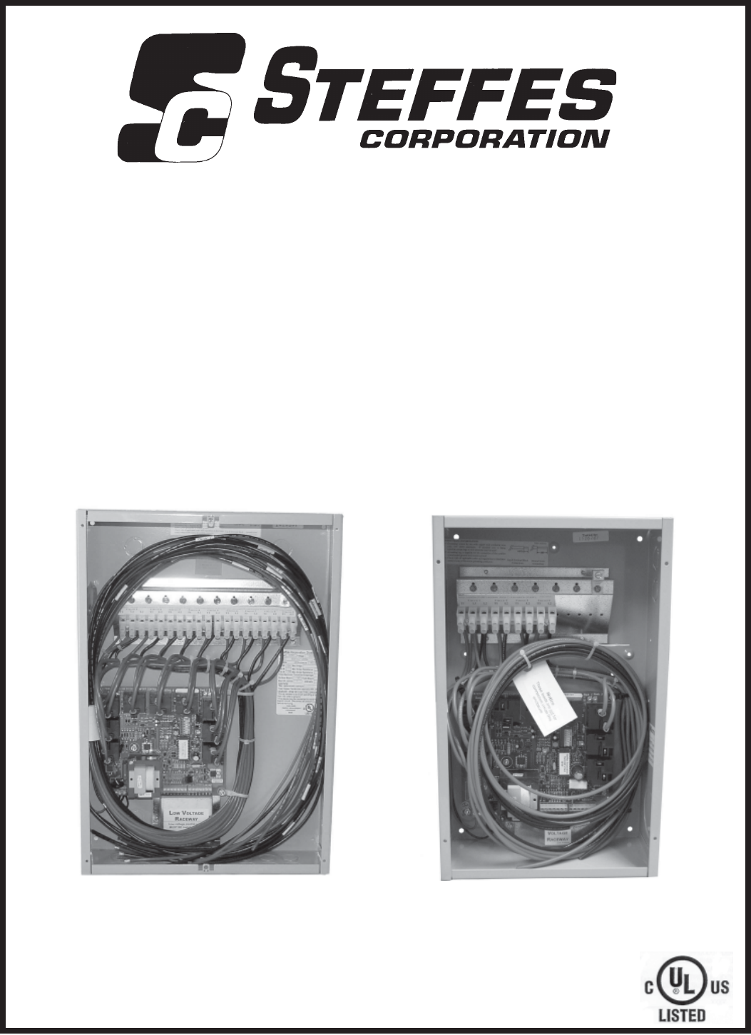
CCRP9 "Commitment to Innovation" OPERATION & INSTALLATION GUIDE FOR Comfort Control Relay Panel (CCRP) Off-Peak System Control 9 Pole CCRP 4 Pole CCRP (Applicable to Software Version 14.0-14.
IMPORTANT The equipment described herein is intended for installation by a qualified technician in accordance with applicable local, state, and national codes and requirements. This manual should be retained by the owner upon completion of the installation and made available to service personnel as required. Disclaimer: Conditions may occur which cause the power line carrier transmitter and receivers to have difficulties communicating; therefore, not operating properly.
TC Table of Contents Comfort Control Relay Panel (CCRP) General Operation ................................................................................................................................... 1 Electrical Loading Limits ...................................................................................................................... 1 Features .................................................................................................................................................
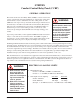
STEFFES Comfort Control Relay Panel (CCRP) GENERAL OPERATION The Steffes Comfort Control Relay Panel (CCRP) is a device used for the control of electrical loads such as ETS heaters, water heaters, baseboards, electric furnaces, dryers, dishwashers, hot tubs, ceiling cable, etc. The CCRP can control up to nine (9) electrical circuits using its internal, board mounted relays.
CCRP CONTINUED...
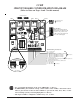
CCRP CIRCUIT BOARD CONFIGURATION DIAGRAM (Refer to Notes on Pages 4 and 5 in this manual) Override Jumper (J9) On 1 2 3 Off 1 (See Note 6) LED 3 2 3 LED 6 LED 4 LED 5 Relay 7 Relay 3 Relay 4 Relay 5 1 2 3 1 2 3 On Override Jumper (J8) (See Note 6) Off Relay 6 Relay 2 Relay 8 Dip Switches Relay 9 Relay 1 Microprocessor Software (Refer to Dip Switch Settings in this manual.) Note direction of dip switch for "ON" position versus "OFF" position.
NOTES (Refer to the Circuit Board Configuration Diagram on page 3 of this manual.) NOTE 1: Line Voltage Connections This device can be powered with 120V or 208V/240V. In most applications, optimum performance is achieved when connected to 208V/240V. The CCRP is equipped with a factory installed wiring and is configured for 208V/240V. If the CCRP is to be connected to 120V, the transformer tapping MUST be changed.
NOTES CONTINUED... NOTE 4: Overrides (Optional, Power Company Permitting) / Multiple Control Strategies With the addition of the 3-zone override module to the CCRP, peak override of 6 of the 9 circuits is possible. If enabled, relays 1, 2, 3, 7, 8, or 9 can be used in 60-minute intervals during a peak control period, if desired. Devices controlled by relays 4, 5, and 6 can never be overridden. Installation instructions for this feature are provided with the override module. (Order item #1302060.
DIP SWITCH SETTINGS (If using the built-in PLC Transmitter Feature for Control) If the power line carrier (PLC) transmitter in the CCRP is being utilized for the control of the 1000 and/or 2000 series heater(s), dip switches 1, 2, 3, 4, 6, and 8 on the heater’s circuit board MUST be set to the "OFF” position.
DIP SWITCH SETTINGS CONTINUED... DIP SWITCH 6: INDEPENDENT PLC AND RELAY CONTROL This dip switch allows for power line carrier control of devices independent of the relay circuits. FACTORY DEFAULT SETTING = OFF Off = Relay circuits will be controlled at the same time as the PLC transmitter controlled devices. The relays are coupled with the “P” input terminal. On = Relay circuits can be controlled separate from the PLC transmitter controlled devices. The relays are coupled with the “E” input terminal.
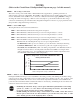
TYPICAL SYSTEM WIRING DIAGRAM - NINE POLE (Utilizing PLC Control with the Steffes 1000/2000/2100 Series Room Units) Field Installed Wiring (See Note 3) TO CONTROLLED LOAD (30 Amp Circuit Maximum) Only if Anticipated Peak Is Being Utilized By The Power Company.
TYPICAL SYSTEM WIRING DIAGRAM - FOUR POLE (Utilizing PLC Control with the Steffes 1000/2000/2100 Series Room Units) Field Installed Wiring (See Note 3) TO CONTROLLED LOAD (30 Amp Circuit Maximum) Only if Anticipated Peak Is Being Utilized By The Power Company.
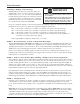
RELAY TRIGGERING SCHEMATIC (For Use with Multiple Rate/Control Strategies Only) Jumper 9 Terminal strip connections Input Voltage OVS - Override Switch OVR - Override Hot OVC - Override Common OV4 - Relays #7, 8, and 9 Override or Multiple Control Input OV3 - Relay #3 Override/Multiple Control Input OV2 - Relay #2 Override/Multiple Control Input OV1 - Relay #1 Override/Multiple Control Input C - Low Voltage Common E - Room Temperature Set Back or Independent Relay Control A - Anticipated Peak P - Signa
Comfort Control Relay Panel (CCRP) Relay 2 Relay 1 Override Jumper (J9) CIRCUIT 2 Relay 4 CIRCUIT 4 Relay 5 CIRCUIT 3 (See Note 2) Relay 6 CIRCUIT 5 CIRCUIT 6 CIRCUIT 7 (See Note 1) CIRCUIT 9 Override Jumper (J8) (See Note 3) On 1 2 3 CIRCUIT 8 Relay 9 OVS OVR OVC OV4 OV3 OV2 OV1 Microprocessor C E A P R OS OS Transformer Connect to "R" Connect to "P" Connect to "E" Connect to "C" 1. Dip switch 6 must be "ON" to enable independent relay control.
W Warranty WARRANTY STATEMENT Steffes Corporation (“Steffes”) warrants that the Steffes Comfort Control Relay Panel device is free from defects in materials and workmanship under normal use and service.