
Installation Guide Owner's manual

H/E
RC
Outdoor
Outdoor
COM
NC
NO
W/
D6
RLY1
To Control Board
D4
Fid 2
Blower
To Control Board
Air
C3
P10
R1
R2
P11
D5 D7 D3
Water
Y1 Y2
W E
D2
J3
J2
J1
P5
D1
J4
P6
P4
Speed
Blower
J6
J5
C
B
A
D
P2P3
Y1
AUX
OGY2 Y1
2
Y2
22
O
CR
Comfort Plus
LV Circuit Board
P7
P1
P9P8
APPRP
Peak Aux.
Inputs
Relay
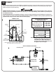
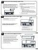
The Y1/Y2 Jumper must be installed
Honeywell TH5220D
Aux
ELCGO/B RYRc
Hydronic Heat Thermostat, Zone
Valve, End Switch, or Pump Control
C - Low Voltage Common
R - Low Voltage Hot
O - Reversing Valve
Y - Compressor
To Heat Pump
Outdoor Sensor
The W/E Jumper must be removed
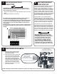
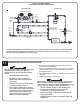
STAND ALONE FURNACE APPLICATION WITH UNCONTROLLED AIR CONDITIONER
SINGLE STAGE HEAT PUMP APPLICATION
Thermostat
Stage
Thermostat
Output
Heat
Pump
Stage
% of
Selected
CFM
Heat Call Status
on Digital
Display*
Discharge Air
Temperature
Target
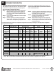
1 Y1/G 1 100% HC1 L048
2 Aux/Y1/G 1 100% HC2 L049
Fan Only G 0 400 cfm HCF N/A
Cool Y1/G/O 1 100% COOL N/A
Hydronic
Heat Control
H/E N/A N/A HC3 N/A
SINGLE STAGE HEAT PUMP
Contractor Use Only
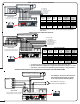
TWO STAGE HEAT PUMP APPLICATION
Thermostat
Stage
Thermostat
Output
Heat
Pump
Stage
% of
Selected
CFM
Heat Call
Status on
Digital Display*
Discharge Air
Temperature
Target
1 Y1/G 1 50% or 70%** HC1 L048
2 Y1/Y2/G 2 100% HC1 L048
3 Aux/Y1/Y2/G 2 100% HC2 L049
Fan Only G 0 400 cfm HCF N/A
Cool 1 Y1/G/O 1 50% or 70%** COOL N/A
Cool 2 Y1/Y2/G/O 2 100% COOL N/A
Hydronic
Heat Control
H/E N/A N/A HC3 N/A
Contractor Use Only
TWO STAGE HEAT PUMP
If installing a mechanical thermostat or
thermostat with anticipator, a resistor
kit is required (Order Item #1190015).
* If multiple inputs are active, system will display highest Heat Call values.
** Systems built before 1/1/2011 are configured for 50% airflow in Stage 1. For more
information, refer to Instruction #1200601-High Speed Stage 1 Relay Installation.
* If multiple inputs are active, system will display highest Heat
Call values.
IMPORTANT
IMPORTANT
IMPORTANT
A
B
C
D
W / E
Y1 / Y2
J1
J2
J3
J4
J5
J6
Blower
Speed
A
B
C
D
W / E
Y1 / Y2
J1
J2
J3
J4
J5
J6
Blower
Speed
A
B
C
D
W / E
Y1 / Y2
J1
J2
J3
J4
J5
J6
Blower
Speed
P8 P9
Aux.
COM
NC
AP
NO
Relay
Honeywell TH5220D
Aux
LY2
GCO/B
Hydronic Heat Thermostat, Zone
Valve, End Switch, or Pump Control
RYR c
C - Low Voltage Common
Outdoor Sensor
O - Reversing Valve
R - Low Voltage Hot
To Heat Pump
Y1 - Compressor
Y2 - Compressor Stage 2
The W/E Jumper must be removed
The Y1/Y2 Jumper must be removed
Inputs
Peak
P1
P7
LV Circuit Board
Comfort Plus
To Control Board
P10
Fid 2
RLY1
D4
D6
R2
R1
P11
D3D7D5
W E
Y1 Y2
Water
Air
P6
D1
P5
Blower
J3
J1
J2
J4
D2
To Control Board
P3
C
Blower
Speed
A
B
J5
J6
C3
D
P4
P2
O
W/
Y1
AUX
Y2
G
Outdoor
Outdoor
Y2
R
H/E
2
Y1
C
O
22
RP P
R C
W/
NO
NC
COM
Outdoor
Outdoor
CR
H/E
The Y1/Y2 Jumper must be installed
RLY1
D6
To Control Board
Fid 2
D4
Blower
To Control Board
O
D3
R2
R1
D7D5
P11
W E
Y1 Y2
Water
J4
D1
P5
J1
J2
J3
P10
P6
D2
D
A
B
C
C3
J5
J6
Blower
Speed
P4
P3
AUX
Y2 GY1
O
22
Y2Y1
R
Air
LV Circuit Board
Comfort Plus
P7
P8
P2
P1
C
P9
RP
2
APP
Aux.
Relay
Peak
Inputs
G
TH5110D
R
C
W
Y
Honeywell
Rc
(If being used in the application)
Air Conditioner Connections
C
Y
The W/E Jumper must be removed
Hydronic Heat Thermostat, Zone
Valve, End Switch, or Pump Control