
Installation Guide User guide

The W/E Jumper must be installed
Air
To Control Board
D4
Fid 2
Blower
C3
R1
R2
P10
D6
RLY1
P11
D5 D7 D3
Water
W E
Y1 Y2
P5
J3
J2
J1
D2
J4
D1
P6
P4
C
B
A
D
Speed
Blower
J6
J5
P3 P2
P8 P9
Air Conditioner
Connections
(If being used in the
application)
The Y1/Y2 Jumper must be installed
Y
W
G
C
TH5110D
Honeywell
R
cR
Y
Outdoor
W/
Y1AUX G OY2 Y1
RC
H/E
2
O
22
Y2
COM
Outdoor
NO
APPRP
NC
Aux.Peak
Inputs
Relay
C
P1
To Control Board
Comfort Plus
RC
LV Circuit Board
P7
9
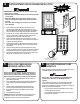
LOW VOLTAGE PEAK
CONTROL CONNECTIONS
If utilizing a Steffes Time Clock
Module or Power Line Carrier control,
refer to the installation instructions
provided with the device.
10
LOW VOLTAGE OUTDOOR SENSOR
CONNECTIONS
1. Route low voltage wire from load
control device to terminal block.
2. Connect field wiring to RP and P
positions.
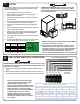
The outdoor temperature sensor can be installed by wiring it directly to the
system or to the Steffes power line carrier (PLC) system.
Direct Wired:
1. Mount outdoor sensor in a location where it can accurately sense
outdoor temperature.
2. Route low voltage wire from outdoor sensor to electrical
compartment:
Outdoor sensor wire MUST NOT be combined with other control
wiring in a multi-conductor cable.
Seal external wall openings.
Outdoor sensor lead can be extended to 250 ft.
Unshielded Class II (thermostat) wire can be used provided it is
segregated from any line voltage wiring.
3. Connect outdoor sensor wires to the two "OUTDOOR" positions of the
low voltage terminal block.
If connecting to the Steffes
power line carrier system,
follow the installation instruc-
tions in the PLC systems
Owners and Installers Guide.
LOW VOLTAGE ROOM THERMOSTAT CONNECTIONS
A 24 VAC thermostat must be used (digital recommended).
1. Disconnect power to the Comfort Plus system.
2. Route low voltage wires from the thermostat to the
Comfort Plus System.
3. Insulate thermostat wire wall opening if necessary and
attach thermostat to the wall. When using a mechani-
cal thermostat or thermostat with anticipator, resistor
kit #1190015 must be installed to ensure proper
operation.
4. Connect low voltage wires from thermostat into
terminal block as shown.
11
12
SOFTWARE CONFIGURATION AND INSTALLERS FINAL CHECKOUT
To ensure proper operation, the system software must be configured for the application. Refer to the Configuration Menu in
the Owner's and Installer's Manual or to the Configuration Guide provided by your local power company. Also, complete the
Installer's Final Checkout Procedure found in the Owner's and Installer's Manual.
Part No. 1200283-6
3050 Hwy 22 North w Dickinson, ND 58601-9413 w www.steffes.com
NOTE: For detailed heat call information, reference the
Owner's and Installer's Manual.
P8 P9
Aux.
COM
NC
AP
NO
Relay
Outdoor Sensor
O
W/
Y1AUX Y2 G
Outdoor
Outdoor
Y2
R
H/E
2
Y1
C
O
22
RP P
R C
P1
P11
D3D7D5
W E
Y1 Y2
Water
Air
P6
D1
P5
Blower
J3
J1
J2
J4
D2
To Control Board
P3
C
Blower
Speed
A
B
J5
J6
C3
D
P4
P2
Inputs
Peak
P7
LV Circuit Board
Comfort Plus
To Control Board
P10
Fid 2
RLY1
D4
D6
R2
R1
P9
Aux.
COM
NC
AP
NO
Relay
P8
O
W/
Y1AUX Y2 G
Outdoor
Outdoor
Y2
R
H/E
2
Y1
C
O
22
RP P
R C
P1
Inputs
Peak
P7
LV Circuit Board
Comfort Plus
To Control Board
P10
Fid 2
RLY1
D4
D6
R2
R1
P11
D3D7D5
W E
Y1 Y2
Water
Air
P6
D1
P5
Blower
J3
J1
J2
J4
D2
To Control Board
P3
C
Blower
Speed
A
B
J5
J6
C3
D
P4
P2
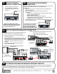
Dry Contact Peak
Control Switch
Single Stage Heat Pump Application
IMPORTANT
A
B
C
D
W / E
Y1 / Y2
J1
J2
J3
J4
J5
J6
Blower
Speed
Stand Alone Furnace Application with Uncontrolled
Air Conditioning
IMPORTANT
A
B
C
D
W / E
Y1 / Y2
J1
J2
J3
J4
J5
J6
Blower
Speed
Two Stage Heat Pump Application
IMPORTANT
P8
Peak Aux.
Inputs Relay
The Y1/Y2 Jumper must be installed
Honeywell TH5220D
Aux
ELCGO/B RYRc
C - Low Voltage Common
R - Low Voltage Hot
O - Reversing Valve
Y - Compressor
To Heat Pump
Outdoor Sensor
The W/E Jumper must be installed
P9
H/E
RC
Outdoor
Outdoor
COM
NC
NO
W/
D6
RLY1
To Control Board
D4
Fid 2
Blower
To Control Boar d
Air
C3
P10
R1
R2
P11
D5 D7 D3
Water
Y1 Y2
W E
D2
J3
J2
J1
P5
D1
J4
P6
P4
Speed
Blower
J6
J5
C
B
A
D
P2P3
Y1AUX OGY2 Y1
2
Y2
22
O
CR
Comfort Plus
LV Circuit Board
P7
APPRP
P1
Honeywell TH5320U
RRYCO/BG
Aux
Y2
Y2 - Compressor Stage 2
C - Low Voltage Common
cL
R - Low Voltage Hot
O - Reversing Valve
To Heat Pump
Y1 - Compressor Stage 1
The Y1/Y2 Jumper must be removed
W/
NO
NC
COM
Outdoor
Outdoor
CR
H/E
RLY1
D6
To Control Board
Fid 2
D4
Blower
To Control Board
O
D3
R2
R1
D7D5
P11
W E
Y1 Y2
Water
J4
D1
J1
J2
J3
P10
D2
D
A
B
C
C3
J5
J6
Blower
Speed
P4
P3
AUX
Y2
G
Y1
O
22
Y2Y1
Air
LV Circuit Board
Comfort Plus
P1
P2
RP
2
APP
Aux.
Relay
Peak
Inputs
The W/E Jumper must be installed