
Installation Guide User guide

44
LINE VOLTAGE ELECTRICAL CONNECTIONS
HAZARDOUS HAZARDOUS
HAZARDOUS HAZARDOUS
HAZARDOUS
VV
VV
V
OLOL
OLOL
OL
TT
TT
T
AA
AA
A
GE:GE:
GE:GE:
GE:
Risk of Risk of
Risk of Risk of
Risk of
electric shoc electric shoc
electric shoc electric shoc
electric shoc
k.k.
k.k.
k.
Can cause injur Can cause injur
Can cause injur Can cause injur
Can cause injur
y or deay or dea
y or deay or dea
y or dea
th.th.
th.th.
th.
DO NO DO NO
DO NO DO NO
DO NO
T enerT ener
T enerT ener
T ener
gizgiz
gizgiz
giz
e the heae the hea
e the heae the hea
e the hea
terter
terter
ter
until installation is complete. Equipment must be installed by a qualified technician in accordance withuntil installation is complete. Equipment must be installed by a qualified technician in accordance with
until installation is complete. Equipment must be installed by a qualified technician in accordance withuntil installation is complete. Equipment must be installed by a qualified technician in accordance with
until installation is complete. Equipment must be installed by a qualified technician in accordance with
applicable local, state, and national codes and regulations.applicable local, state, and national codes and regulations.
applicable local, state, and national codes and regulations.applicable local, state, and national codes and regulations.
applicable local, state, and national codes and regulations.
Risk of fire. Can cause injury or death. Poor or marginal electrical connections will cause the connections
to overheat and fail. Use extreme caution when making all electrical connections.
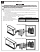
1. After establishing placement of the heater, mount a field connection junction box either beside or behind the heater or mounted
in the floor below the heater.
• The junction box MUST remain accessible for future service to the heater and MUST be sized in accordance with
all applicable electrical codes and regulations.
• Connections shown are for systems with a 240V/208V blower/control circuit. Refer to the Unit Identification Label
on the lower left side panel of the heater for proper voltage configuration.
2. Route the proper size and type of wire from the
breaker panel to the junction box.
3. Connect the field wiring to the wiring harness
(umbilical cord) of the heater inside the junction box.
4. Label the breaker panel accordingly.
WARNINGWARNING
WARNINGWARNING
WARNING
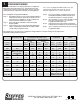
Wiring Harness (Umbilical Cord ) Color Code Chart
WIRE COLOR CIRCUIT DESCRIPTION
Black Circuit feed for two of the four heatin
g
elements
Red Circuit feed for two of the four heating elements
Blue and Blue/Black Circuit feed for the blower and heater's control
Green Ground
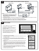
MULTIPLE CIRCUIT CONNECTIONS
GREEN
MULTIPLE
CONNECTED
CIRCUIT
4
240VAC SOURCE
BREAKER PANEL
BLACK
BLUE/BLACK
BLUE
BLACK
RED
RED
2
3
1
6
5
SINGLE CIRCUIT CONNECTIONS
RED
RED
BLACK
BLUE/BLACK
GREEN
3
15
30
6
BLACK
BLUE
CIRCUIT
SINGLE
CONNECTED
BREAKER PANEL
41
2
20
15
5
20
15
240VAC SOURCE