
User's Manual


UM000004-1_3 - Micro.sp (Q)Be
©
Station System v4 User Manual
8
Ste Industries
Via privata Oslavia 17/8D – 20134 Milano
www.ste-industries.com – info@ste-industries.com
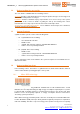
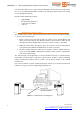
The following connectors are provided:
• 1 USB connector for (Q)Be© system configuration (only for Master tower)
• 1 BNC for 434 MHz (Q)Be© TPMS antenna (both Master and Slave)
• 1 power supply connector to connect the Mother Board to the battery (both
Master and Slave)
The plastic case is mounted inside the tower on the upper rack of the metal bracket.
To facilitate maintenance and replacement, it is designed such as all the wirings and
connectors are easily accessible.
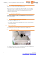
1.5.2 Metal Bracket
The Metal bracket consists of 3 racks.
Top rack is provided with holes to mount and hold in place 434MHz TPMS receiver antenna.
Mid rack with holes to mount and hold in place (Q)Be© mother boards.
Bottom rack houses battery pack.
The metal brackets are painted in black.
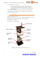
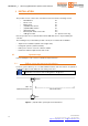
Figure 3 - (Q)Be© metal bracket with installed components
Battery pack
(
Q)Be
©
Mother
Board
USB port
plastic cap
Power cable
connector
434MHz antenna
(Q)Be© metal bracket
Bracket ground
plate
External shell
fixing plate
External shell
fixing plate