
User's Manual

UM000004-1_3 - Micro.sp (Q)Be
©
Station System v4 User Manual
20
Ste Industries
Via privata Oslavia 17/8D – 20134 Milano
www.ste-industries.com – info@ste-industries.com
2.1.12 GSM Test
Note: this test applies to both GSM and 3G modules.
Before starting the test, it is recommended to download and install Device Explorer to
monitor data sent to the server. It can be downloaded from https://github.com/Azure/azure-
iot-sdk-csharp/releases/.
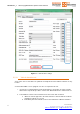
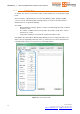
1. Open Device Explorer, select Configuration tab and copy the following string into the
“IoT Hub Connection String” window:
HostName=tirematics-iot.azure-
devices.net;SharedAccessKeyName=iothubowner;SharedAccessKey=Z6ip+HnDiugv0C
2it5OsxJDS55rJ0cUPCmuK18e5Xjw=
Click the Update button and check that the program responds by opening the “Setting
updated successfully” popup window.
Select Data tab and choose the same Device ID written in the Json POST Header entry
(see section 2.1.8). Default Device ID is FL001_G01. You may select another Device
ID, provided that you first update the corresponding entry in the Json POST Header as
explained in 2.1.8. Also EMS Token can be modified, if required.
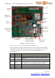
2. On Gate Interface V4, to start GSM test click the “Test GSM” button, as shown in Figure
14. System status will change to “Testing GSM” and results are printed on the screen
below.
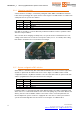
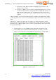
GSM test may take several minutes. During this time, if communication with
Bridgestone server is successful, you should see data transfer on the Event Hub Data
window as shown in Figure 15.
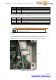
If it is successful, the result “GSM: OK” is printed (see Figure 16). Click “Stop GSM
Test” button to end this test procedure.
(optional) After a successful GSM test click again on the “Test Towers” button as
explained in section 2.1.11. The numbers of TPMS received by Master and Slave
towers “TPMS RX” should be either 0 or lower than the previous readings, meaning that
TPMS data has been successfully transferred to the remote server.
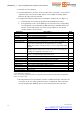
In case of any error, the test is interrupted and the message “GSM: ERROR” is printed
(see Figure 17). Click “Stop GSM Test” button to end this test procedure and retry after
troubleshooting.
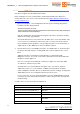
Possible causes of error are listed in the table below.
Error case Error description / possible cause
Power ON GSM Power supply failure or HW failure.
Serial Communication with GSM device HW failure.
Verbose Mode Activation GSM/3G failure.
Choice Band Plan GSM network Wrong GSM/3G band selection.
Connection to the GSM network GSM/3G network may be temporarily
unavailable.
APN settings Check APN settings in section 2.1.8 and enter