
User's Manual

UM000004-1_3 - Micro.sp (Q)Be
©
Station System v4 User Manual
15
Ste Industries
Via privata Oslavia 17/8D – 20134 Milano
www.ste-industries.com – info@ste-industries.com
2.1.7 Connecting power supply
Warning: Do not open the battery box.
Do not remove the battery box from the metal bracket.
CAUTION: risk of explosion if battery is replaced by an incorrect type.
Dispose of used batteries according to the instructions.
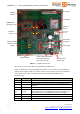
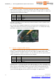
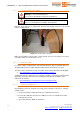
Align the power cable to the appropriate direction and carefully connect it to the mother
board (see figure below).
Figure 10 – Power cable connection
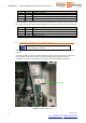
Make sure that SW1 is in ON position. Open the plastic box, press PL1 button (it is located
near Status LEDs) and check that DL1 is on.
2.1.8 Software setup
In order to configure (Q)Be© station, VCP (Virtual COM Port) driver for FT230X chip, if not
already installed, must be downloaded from FTDI website and installed on your PC.
The latest version of VCP driver setup executable can be downloaded at the following link:
http://www.ftdichip.com/Drivers/CDM/CDM20828_Setup.exe
Installation instructions depend on your computer’s operative system. Please download the
appropriate instruction manual from the following link and follow the installation steps
indicated in the manual.
http://www.ftdichip.com/Support/Documents/InstallGuides.htm
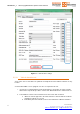
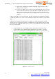
2.1.9 System Configuration
After FTDI driver has been installed successfully, please follow the next steps to configure
(Q)Be© system:
1. Unscrew by hand the USB port plastic cap of (Q)Be© master tower.
2. Connect the USB cable from any free USB port of the PC to (Q)Be© master tower
USB Type B connector.
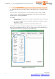
3. Open “Gate Interface” Windows application.