
User's Manual

UM000004-1_3 - Micro.sp (Q)Be
©
Station System v4 User Manual
13
Ste Industries
Via privata Oslavia 17/8D – 20134 Milano
www.ste-industries.com – info@ste-industries.com
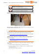
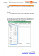
2.1.4 Detection sensitivity
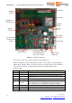
Vehicle detection sensitivity is controlled by setting DIP switch SW6 on both Master and Slave
towers before powering up the system. Please refer to Figure 7 for SW6 location. You will need a
small pointed tool to operate the switches.
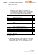
Switch 1 Switch 2 Sensitivity
Off Off Highest
Off On High (default option)
On Off Medium
On On Low
Note that it is possible to set levels differently on Master and Slave in order to optimize vehicle
detection in any installation.
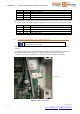
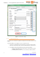
Also note that, when changing sensitivity levels, the system must be restarted before the new
settings can be taken into account. Disconnect power cable (see 2.1.7 for details) after setting
DIP switches and wait a few seconds until reconnecting it.
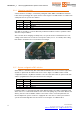
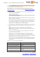
Figure 8 – Setting DIP switches
2.1.5 System configuration DIP switches
Slave address is determined by DIP switch SW4 and identifies the role of a tower in (Q)be Gate
System as explained in the table below. Please refer to Figure 7 for SW4 location. Default
configuration includes only Master and Slave 1: the other two Slave units are optional. This DIP
switch is programmed in factory and should never be changed.
Switch 1 Switch 2 Identifier
On On Master
On Off Slave 1
Off On Slave 2
Off Off Slave 3
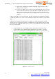
Installation address is determined by DIP switch SW5 and defines the address that Master and
Slave units use to communicate between each other. Data polling only occurs when Master and
Slave(s) have the same installation address. This feature can be used in the particular case
when multiple Gate systems need to be equipped in the same area, in order to prevent those
systems from interfering with each other. Please refer to Figure 7 for SW5 location.