
User's Manual

UM000004-1_3 - Micro.sp (Q)Be
©
Station System v4 User Manual
12
Ste Industries
Via privata Oslavia 17/8D – 20134 Milano
www.ste-industries.com – info@ste-industries.com
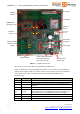
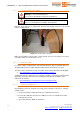
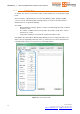
Figure 7 – (Q)Be© mother board
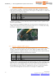
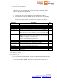
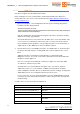
The functions of each status LED are explained in the table below.
LEDs are disabled in normal operating mode in order to save power thus increasing battery
lifetime. By pressing PL1 button (see picture above for PL1 position) they can be enabled for
some minutes: this feature is required to monitor the system during initial setup or
troubleshooting.
LED ID Function Description
DL1 3VCC ON when main power supply is applied.
DL2 MAGN Long blink (1 sec) when a vehicle is detected.
DL3 RX ON
ON when Micro.sp receiver is powered up. Activated by vehicle
detection.
DL4 TPMS DEC Short blink each time a valid TPMS sensor is received.
DL5 RF LINK
ON when the device is ready for Master-Slave data transfer.
During this phase it turns rapidly OFF (and then ON again) each
time a data packet is exchanged between Master and Slave.
DL6 CPU ON when CPU is active (Master only)
DL7 GPRS ON ON when 3G module is powered up (Master only)
DL8 GPRS STAT 3G status and alarms LED (Master only – currently not used)
Battery p
ower
supply input
Vehicle detection
sensitivity switch
(SW6)
Vehicle detector
Status LEDs
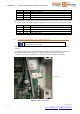
SIM card
holder
3G module
Micro.sp
receiver
92
0
MHz data
exchange circuit
920
MHz
antenna
3G antenna
CPU
OFF
ON
Insert card
this side
Power supply switch
SW1
:
ON: battery (default)
OFF: power via USB
SW4
SW5
LED enable
button PL1
OFF
SW7
O
N
O
FF
ON