
User's Manual


UM000004-1_3 - Micro.sp (Q)Be
©
Station System v4 User Manual
10
Ste Industries
Via privata Oslavia 17/8D – 20134 Milano
www.ste-industries.com – info@ste-industries.com
2 INSTALLATION
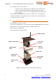
The product consists of two towers. Check that each tower has the following content:
• Metal Bracket nr.1
• Plastic cover nr.1
• Battery pack nr.1
• (Q)Be© mother board nr.1
• (Q)Be© TPMS antenna nr.1
• Shells fixing bolts nr.3
• Bracket plate dowels and screws nr.4
• USB type B cable nr.1 (master tower only)
Note: the product does not include data network SIM card, it has to be provided by the
customer.
The following tools (not included in product content) are needed for the installation:
• Square head screwdriver (Ø5mm, max length 12cm)
• Hexagonal spanners (Ø16mm, Ø8mm)
• Drill to pierce holes in concrete or tarmac, Ø8mm
• Hammer to fit bracket plate dowels and screws
2.1 System setup
Follow carefully the next sections for detailed setup instructions.
2.1.1 (Q)Be
©
system placement and installation
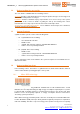
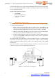
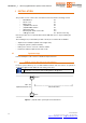
For best system efficiency, it is recommended that master and slave towers are placed as
shown in the figure below, with front sides facing each other.
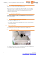
Note: Towers shall be first powered on and configured correctly, as
explained in next sections, before fixing them to the ground.
Figure 5 - (Q)be© station system placement instructions
Master
Slave
Min. 3m
Optimum distance
5m
Vehicle direction