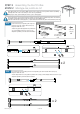
B RIC FA 6 Gazebo GZ584B Assembly Instructions Mode de montage 10’ 14’ 7’’ 12’ 9’ 8 ’’ 4’’ ’ 11’ Systems Trading Corporation 450 7th Avenue Suite 2809, New York, NY 10123 Customer service: (877)782 4482 Email: easygrow@stcaustin.com www.stcny.
Introduction Thank you for purchasing the Gazebo GZ584. When properly assembled and maintained, this gazebo will provide many years of enjoyment! These instructions include helpful hints and important information needed to safely assemble and properly maintain the gazebo. Please read these instructions completely before you begin. Our patented gazebo has been designed for easy assembly. All steps can be completed by a team of two people. The assembly should take about two hours.
Table of Contents Safety Advice • • • • • • • • • • The gazebo must be positioned and fixed on a flat level surface. Dispose of all plastic bags safely. Keep them out of the reach of children. Keep children and pets away from the assembly area until the work is completed. Always wear shoes, gloves and safety goggles when working. Take special care not to touch overhead power lines with the aluminium profiles. Do not attempt to assemble the gazebo in windy or wet conditions.
List of Parts / Liste de pièces The gazebo is shipped in two cartons. These cartons are heavy. Be careful when lifting them. Wear proper safety gear including work shoes, gloves and goggles. The parts are identified by removable stickers. Place all the parts for each step in staging areas, checking that you have all parts as you go. If any parts are missing or damaged, contact STC customer service before beginning assembly: Customer service: (877)782 4482 Le gazebo est livré dans deux cartons.
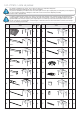
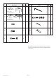
Profile / Profil Part / Pièce No. 18 Qty Step Qté Etape No. 1 8 24 12 1 8 25 12 Part Pièce Qty Step Qté Etape Fabric canopy Couverture de tissu 19 Fabric canopy Couverture de tissu 21 36 26 1 22 32 28 1 23 8 We included some extra screws and bolts for your convenience. Pour votre commodité, nous avons inclus un supplément de vis et de boulons www.stcny.
STEP 1 Assembling the Corner Profiles ÉTAPE 1 Montage des profils de coin Place all the parts on a level surface. Make sure the pieces are in the correct positions before assembling. Carefully follow the order of assembly to ensure an easy installation. Wear proper safety gear including work shoes, gloves and goggles. Placer toutes pièces sur une surface de niveau. Assurez-vous que les pièces sont dans leur position correcte avant assemblage.
STEP 2 Assembling the Roof Profiles ÉTAPE 2 Montage des profils de toit Place all the parts on a level surface. Make sure the pieces are in the correct positions before assembling. Carefully follow the order of assembly to ensure an easy installation. Wear proper safety gear including work shoes, gloves and goggles. Placer toutes pièces sur une surface de niveau. Assurez-vous que les pièces sont dans leur position correcte avant assemblage.
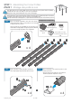
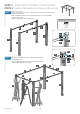
STEP 3 Attaching Roof Profiles to Corner Profiles ÉTAPE 3 Fixation des profils de toit aux profils de coin 3.A Attach long roof profile sets (2,3) to corner profiles (1) as shown. Fasten with bolts (22). Repeat to make two sets. Fixer l’ensemble de profil de toit court (2,3) aux profils de coin (1) comme indiqué. Fixer avec des vis (22). Répétez l’opération pour faire deux ensembles. Components / Composants 2 Screw (22) Vis (22) 3 3 2 x 32 1 22 1 1 1 22 1 22 2 3.
STEP 4 Attaching the Roof Connectors to Roof and Corner Profiles ÉTAPE 4 Fixation des raccords de toit aux profils de toit et profils de coin 4.A Attach roof connectors (16) to corner profile covers (15) and roof profiles (2) and (4) as shown. Fasten with bolts (21). Fixer les connecteurs de toit (16) aux bouchons de profil (15) et aux profils de toit (2) et (4) comme indiqué. Fixer avec des boulons (21).
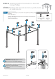
STEP 5 Attaching the Corner Roof Gables ÉTAPE 5 Fixation des pignons de coin de toit IMPORTANT: The roof gable profiles (6) have small protrusions (spring buttons) underneath. The end with the protrusions is connected to the top gable connector (13). The roof gable extension (11) has a small protrusion underneath which will snap into one of the holes in roof gable extension (9) while stretching the canopy. IMPORTANT: Les profils de pignon de toit (6) ont de petites saillies (boutons à ressort) en dessous.
5.B Connect two roof gable profiles assemblies (6,12) to top gable connector (13) until the small protrusion on their undersides snap into the holes on the underside of top gable connector (13). Connecter deux ensembles de profils de pignon de toit (6,12) au raccord de pignon supérieur(13) jusqu’à ce que les boutonsressort de leur face inférieure s’enclenchent dans les trous du dessous du raccord supérieur de pignon (13).
5.D Using at least two people, slide the other two roof gable assemblies (6,12 - 6,11) into tunnels of top gable connector (13) until the small protrusion on their undersides snap into the holes on the underside of top gable connector (13).
5.E Connect the two roof gable profiles (6,12) and (6,11) to roof connectors (16) on opposite corner profiles (1). Fasten with bolts (23) as shown. Connecter les deux profils de pignon toit (6,12) et (6,11) aux raccords de toit (16) sur les profils de coin opposé (1). Fixer avec des vis (23) comme indiqué. 12 12 6 6 13 6 11/12 23 6 16 6 11 12 9 5.
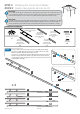
STEP 6 Attaching the Center Roof Gables ÉTAPE 6 Fixation des pignons de centre de toiture IMPORTANT: The roof gable profiles (7,8) have small protrusions (spring buttons) underneath. The end with the protrusions is connected to the top gable connector (13). IMPORTANT: les profils de pignon de toit (7,8) ont des boutons-ressort) sur leur face inférieure. L’extrémité portant ces boutons est connectée au raccord de pignon supérieur(13).
STEP 7 Securing the Gazebo to the Ground ÉTAPE 7 Ancrage du Gazebo au sol Fasten the gazebo frame to the ground, using three spikes (24) for each support plate. Ancrer l’armature du gazebo au sol, à l’aide des trois piques (24) pour chaque plaque de support. Components / Composants Ground spike (24) Pique de sol (24) 1 x 12 24 24 ATTENTION: For special instructions how to secure the gazebo to a concrete floor or wood deck, please turn to page 17.
8.B Using at least two people, place the large canopy (19) carefully over the small canopy (18) and three roof gable profiles (6+12) as shown. Stretch the canopy and slide profiles into fabric pockets in large canopy rim (19). Use TWO hands to pull the fabric backward until the roof profiles slide firmly into the pockets. À l’aide d’au moins deux personnes, placez délicatement la grande couverture (19) sur le petit auvent (18) et les trois profils de pignon de toit (6 + 12) tel qu’illustré.
Optional Securing the Gazebo to a Concrete Floor or Wood Deck Option Ancrage du Gazebo à un semelle de béton ou à une plate-forme en bois Concrete Floor: 1. Using an electric concrete drill, drill holes into the concrete floor, corresponding to the holes in support plates. 2. Insert concrete bolts (25) into the holes and hammer into place, using a mallet. 3. Fasten concrete bolts with washers and nuts. Concrete bolts, washers and nuts (25) Boulons à béton, rondelles et écrous (25) Semelle de béton : 1.
Gazebo GZ584B Assembly Instructions Mode d’montage Visit: http://www.stcny.com for more Lawn and Garden products Visitez nous à : http://www.stcny.com Pour d’autres produits de jardin EasyGrow 8’x 12’ Greenhouse Serre de 8’ x 12’ Systems Trading Corporation 450 7th Avenue Suite 2809, New York, NY 10123 Customer service: (877)782 4482 Email: easygrow@stcaustin.com www.stcny.