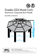
5 Gazebo GZ4 Monte Carlo Aluminium Composite Roof Panels 6’8” 10’3” Assembly Instructions 12’6” 4’6” Systems Trading Corporation 450 7th Avenue Suite 2809, New York, NY 10123 Customer service: (877)782 4482 Email: easygrow@stcaustin.com www.stcny.
Introduction Thank you for purchasing the Gazebo GZ4. When properly assembled and maintained, this gazebo will provide many years of enjoyment! These instructions include helpful hints and important information needed to safely assemble and properly maintain the gazebo. Please read these instructions completely before you begin. Our patented gazebo has been designed for easy assembly. All steps can be completed by a team of four people. The assembly should take about two hours.
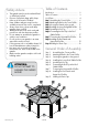
Table of Contents Safety Advice Introduction................................................. Table of Contents......................................... List of Parts.................................................. Step 1 Assembling the Corner Profiles................. Step 2 Attaching the Rails to the Corner Profiles... Step 3 Securing the Gazebo to the ground......... Step 4 Installing the Lower Roof gable Profiles.. Step 5 Assembling the Roof Top..............................
List of Parts The gazebo is shipped in four cartons. These cartons are heavy. Be careful when lifting them. Wear proper safety gear including work shoes, gloves and goggles. The parts are identified by removable stickers. Place all the parts for each step in staging areas, checking that you have all parts as you go. If any parts are missing or damaged, contact STC customer service before beginning assembly: Customer service: (877)782 4482 Email: easygrow@stcaustin.com No.
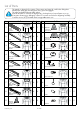
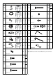
No. Profile Qty Step No. Profile Qty Step 4,5 19 8 5 30 1 5 31 8 5 32 1 5 33 8 7 34 T-shaped Connector 24 5,9 2 2 1 We included some extra screws and bolts for your convenience. Plastic Cap #2 2.5 72 7 Screw M6*12 2.5 96 6 Screw M6*18 48 1 Screw M6*25 www.stcny.
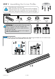
STEP 1 Assembling the Corner Profiles Place all the parts on a level surface. Make sure the pieces are in the correct positions before assembling. Carefully follow the order of assembly to ensure an easy installation. Wear proper safety gear including work shoes, gloves and goggles.
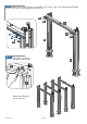
1.B Slide support frames (12) over lower end of corner profiles (1). Attach support plates (13) to corner profiles as shown, using four screws (29) for each plate. 1 1 12 13 29 Leave support frames (12) about 10”over lower end of all eight corner profiles (1) until step 3 (Securing the gazebo to the ground) 1 12 13 13 12 1 www.stcny.
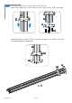
STEP 2 Attaching the Rails to the Corner Profiles Components Rail (2) Outer Roof Connector (25) Screw M6*12 (27) 2.A x 16 x8 x8 Screw M6*18 (28) Plastic Cap #2 (26) x 64 Magnetic Hex Key (34) x1 x 64 Attach one outer roof connector (25) to each rail at pre-drilled screw holes, using screws (27). 27 25 25 2 VIEW FROM SIDE 25 2 VIEW FROM THE TOP ATTENTION: Attach roof connectors facing exactly in the directions shown. x8 www.stcny.
2.B Attach one roof rail (2) to two corner profiles (1) as shown, using screws (28) and supplied magnetic hex key (34) through holes in profile set. 26 28 2 2 26 28 26 1 28 1 2.C Close holes in profile set with plastic caps #2 (26). 2 1 26 1 Repeat step 2.B and 2.C to create four sets. www.stcny.
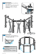
2.D Using 4 people, attach roof profile (2) to corner profiles (1). Fasten with four screws (28) and supplied magnetic hex key (34) on each side. Close holes in profile sets with plastic caps #2 (26). 2 28 26 1 2 2 1 1 1 1 ILLUSTRATION 2.E Using 4 people, continue attaching roof profiles (2) to corner profiles (1) to create the octagonal gazebo base. 45° 45° 45° 90° 90° 45° 135° IMPORTANT: After this step you should place the gazebo frame in its desired location.
STEP 3 Securing the Gazebo to the Ground 3.A Fasten the gazebo frame to the ground, using four spikes (35) for each support plate. Lower support frames (12) to cover support plates (13). Components 1 1 12 Ground spike (35) x 32 35 13 13 Optional Securing the Gazebo to a Concrete Floor or Wood Deck Components Concrete Floor: 1. Using a concrete drill, drill holes into the concrete floor, corresponding to the holes in support plates (13). 2.
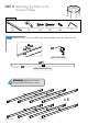
STEP 4 Installing the Lower Roof Gable Profiles Towards center BOTTOM VIEW OF PROFILE (8) Towards outer edge Components ATTENTION: DO NOT ATTEMPT TO ASSEMBLE THIS ALONE ! 4.A Using screws (30) and nuts (31), connect roof gable profiles (8) to roof connectors (14) on top of all eight corner profiles (1). Roof Gable Profile (8) 2102mm x8 Screw (30) x 16 ATTENTION: Nut M6 (31) x 16 Roof profiles, roof panels and gables must be aligned properly during assembly to minimize any possibility of leaking.
STEP 5 Assembling the Roof Top Components Roof Gable Profile (6) 431mm Roof Top Profile (3) 431mm x8 Top Ring (20) Upper Roof Connector (19) x1 x8 x8 Inner Roof Connector (21) x8 BLACK SIDE Top Center Rail Connector (22) Roof Top Cover (15) x1 Screw (30) x 24 5.
5.C Using screws (30) and nuts (31), connect the eight roof gable profiles (6), to upper roof connectors (19) as shown. ATTENTION: Roof profiles, roof panels and gables must be aligned properly during assembly to minimize any possibility of leaking. 31 30 19 6 20 6 6 6 6 19 19 6 6 19 19 19 6 5.D 19 20 6 Using screws (28), connect top center rail connector (22) to roof gable profiles (6) as shown. 20 22 28 VIEW FROM BELOW www.stcny.