WPS-PS POWER SUPPLIES WP-PS9-12VDC -10A WPS-PS9-12VDC -10AUL WPS-PS9-24VAC -12A WPS-PS18-12VDC-18A WPS-PS18-12VDC-18AUL INSTALLATION AND USERS MANUAL Review manual thoroughly before installation. Retain for future reference.
IMPORTANT SAFETY INSTRUCTIONS WARNING: To reduce the risk of fire or electric shock, do not expose this apparatus in or near rain or moisture. 1. Read and keep these instructions for future reference. 2. Do not use this apparatus near water. 3. Clean only with a dry cloth. 4. Do not block any ventilation openings. Install according to manufacturer’s instructions. 5. Do not install near any heat sources such as radiators, heat registers, stoves or other apparatus (Including amplifiers) that produce heat. 6.
TABLE OF CONTENTS 1 Product Overview.................................................................4 1.1 Packing List.........................................................................4 1.2 Features...............................................................................4 2 Connections and Controls...................................................5 3 Installation.............................................................................6 3.1 Mounting.........................................
WPS-PS Power Supplies Installation Manual 1 PRODUCT OVERVIEW 1.1 Packing List (3) Rubber grommets (2) Keys (1) IEC power cord and clip (Non UL Versions) (1) Manual (10) Spare glass fuses in UL versions 1.
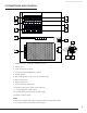
WPS-PS Power Supplies Installation Manual 2 CONNECTIONS AND CONTROLS 9 1 2 10 3 11 4 12 I o 5 6 13 7 8 1. Channel fuses - Glass (UL Versions) or PTC 2. Status LEDs 3. +Volt (Positive) Outputs 4. -Volt Common (Negative) Outputs 5. Power Switch 6. IEC Locking Clip Loops (non-UL versions only) 7. IEC Power Input 8. Main Power Fuse 9. +Volt (Positive) Main Input 10. Spare Power Fuse (Glass Fuse Versions) 11. -Volt (Negative) Main Input 12. Cooling Fan (18 Channel Models Only) 13.
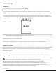
OF R WPS-PS Power Supplies Installation Manual 3 INSTALLATION 3.1 Mounting 1. Locate wall studs using a stud finder (not included). 2. Position the provided template on the wall in the desired location of the WPS-PS. If the location does not allow for this, use a wall molly or anchor with the appropriate weight rating for the WPS-PS. 3. Level the template and mark the wall with the screw locations.
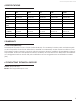
WPS-PS Power Supplies Installation Manual 4 SPECIFICATIONS WPS‐PS9‐12VDC‐ 10A WPS‐PS9‐12VDC‐ 10AUL WPS‐PS9‐24VAC‐ 12A WPS‐PS18‐12VDC‐ 18A WPS‐PS18‐12VDC‐ 18AUL Input 120VAC/60Hz 120VAC/60Hz 120VAC/60Hz 120VAC/60Hz 120VAC/60Hz Output 12V DC 10A 12V DC 10A 24V AC 12A 12V DC 18A 12V DC 18A Channels 9 9 9 18 18 Total Power 120W 120W 288W 218W 216W Max Channel Power 12VDC / 2A 12VDC / 2A 24VAC / 2A 12VDC / 2A 12VDC / 2A Fuse Type PTC Glass PTC PTC Glass Dimensions (H x W
120417-1455 © 2012 Wirepath Surveillance