
Instruction Manual


Pg. 3
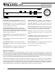
WATTBOX™ 600 Chassis Series Owners Manual
© 2013 Wattbox
™
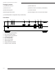
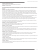
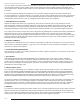
Rear Panel
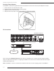
Positioning Options
1. Outlets 1 – 4 – Un-switched (Always On) Isolated Filter
for video/network components
2. Outlet LED Power Indicator
3. Outlets 5 -8 – Switched Isolated lter for audio/auxiliary
4. Outlets 9 – 12 Delayed/Isolated Filter for high current
components
5. Ground Lug
6. Reset Button
7. RJ45 Network Connection (For IP Control)
8. Internet LED Indicator
9. System Status LED Indicator
10. Auto Reboot Enabled Indicator
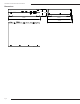
The WattBox™ 600 Series is designed for placement on a shelf or mounting in standard 19” equipment racks. Both rack
ears and feet are included so the decision can be made during installation.
Attach the brackets or feet to the WattBox™ depending on the desired application using the supplied hardware as
illustrated below.
FILTER 3
CONTROL LED 6 CONTROLLED 8
WB-600CH -IPVCE-1 2
FILTER 1 FILTER 2
ALWAYS ON 1 ALWAYS ON 3
ALWAYS ON 2 ALWAYS ON 4
CONTROL LED 1 CONTROL LED 3
CONTROL LED 2 CONTROL LED 4
CONTROL LED 5 CONTROLLED 7
GROUND
LUG
RESET
NETWORK
INTERNE T
SYSTEM STATUS
SAFE VOLTAGE
IN IN
OUT
ON OFF
OUT
AUTO REBOOT
SAFE VOLTAGE
PROTECT ED
GROUNDED
1 32 4 5 6 7 8 9 10
13 15 18 1916 17
11
1412
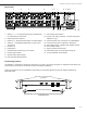
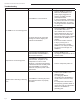
11. Safe Voltage LED indicator
12. Hook & Loop Strap Lockdown – See Securing Power
Adapters on Pg. 4
13. Protected 3GHz coax connections for cable/satellite
14. Protected connections for Ethernet / Telephone
15. Safe voltage switch – Disables Safe Voltage Feature
16. Ground LED indicator
17. Surge Protection LED Indicator
18. Detachable power cord outlet with locking clip
19. 15 Amp resettable circuit breaker
POW ER
VOLTAGE CURRENT USB CHARGING
SAFE VOLTAG E
PROTECTED
GROUNDED
WB-600CH-IPVCE-12
Remove Feet for Rack Mounting
Attach Ears using Supplied Screws
(4 on Each)
Note: Rack ears can be mounted towards the rear of the unit to for easy
connection access.