USER’S MANUAL Intelligent Remote Management Card allows a UPS system to be managed, monitored, and configured Version 1.
Remote Management System TABLE OF CONTENTS Introduction………………………………………………………………………3 Installation Guide………………………………………………………………..5 Web Interface…………………………………………………………………...10 Reset to Default Setting / Recover from a Lost Password…………………17 Firmware Upgrade…………………………………………………….………..18 Trouble Shooting…………………………………………………….………….19 Appendix……………………………………………………………..…………..
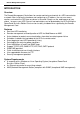
Remote Management System INTRODUCTION Overview The Remote Management Card allows for remote monitoring and control of a UPS connected to a network. After installing the hardware and configuring an IP address, the user can access, monitor, and control the UPS from anywhere in the world. Simply use the web browser of your choice to access your UPS.
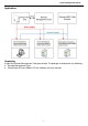
Remote Management System Application: Unpacking Inspect the Remote Management Card upon receipt.
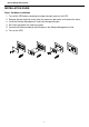
Remote Management System INSTALLATION GUIDE Step 1. Hardware Installation 1. Turn off the UPS before removing the expansion port cover on the UPS. 2. Remove the two retaining screws from the expansion port cover and remove the cover. 3. Install the Remote Management Card into the expansion port. 4. Re-install and tighten the retaining screws. 5. Connect the Ethernet cable to the LAN port on the Remote Management Card. 6. Turn on the UPS.
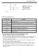
Remote Management System 1 ○ 2 ○ 3 ○ Ethernet connector LINK Indicator RX/TX Indicator Definitions for LED Indicators Link LED color Off On(Yellow) Condition The Remote Management Card is not connected to the Network/ or the UPS is off The Remote Management Card is connected to the Network TX/RX LED color Off The Remote Management Card power is off On(Green) The Remote Management Card power is on Flash - Receiving/transmitting data packet - Reset finished Step 2.
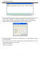
Remote Management System Figure 1. The main window of the “Power Device Network Utility” program. 4. Select the Remote Management Card you are setting up. Click on the Tools menu and select “Device Setup,” or double-click the Remote Management Card you want to configure. 5. You can modify the IP Address, Subnet Mask, and Gateway address for the Device MAC Address listed in the Device Network Settings window, as shown in Figure 2. Figure 2. The network card setting window. 6.
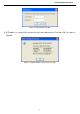
Remote Management System Figure 3. Authentication window. 8. If IP address is successfully set, you will see a message that the IP set up is OK, as shown in Figure 4. . Figure 4. Setup IP Address Successful message.
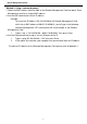
Remote Management System Method 2: Using a command prompt 1. Obtain the MAC address from the label on the Remote Management Card rear panel. Each Management card has a unique MAC address. 2. Use the ARP command to set the IP address. Example: To assign the IP Address 192.168.20.240 for the Remote Management Card, which has a MAC address of 00-0C-15-00-00-01, you will type in the following command prompt from a PC connected to the same network as the Remote Management Card. 1. Type in “arp -s 192.168.20.
Remote Management System WEB INTERFACE Login Account There are two user account types. - Administrator (default username : admin ; default password : admin) - Viewer (default username : guest ; default password : guest) The Administrator can access and control all functions, including enable/disable of the Viewer account. The Viewer’s access allows them read permissions for all functions, but they cannot control or change any settings.
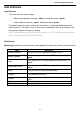
Remote Management System [UPS->Status] Displays basic information about the current UPS status, and the items that are auto-refreshed. item Definition Line Voltage Current input voltage of the utility power. Output Voltage The output voltage of the UPS. Output Frequency The frequency of output power. Output Load The UPS load expressed as a percentage of available total available watts of the UPS Watts. Remaining Capacity The percentage of the current UPS battery capacity.
Remote Management System [UPS->Master Switch] Switches the output power of the UPS to be on or off. Items Definition Reboot UPS Turns the UPS off and back on Turn UPS Off Turns the UPS off. UPS Sleep Turning the UPS off and back on after a period of time. Cancel Switch Cancels a pending action to turn the UPS off. Turn UPS On Turns the UPS on.
Remote Management System Passed: The battery performed normally during the test. None: The UPS has never performed the battery test. Failed: The battery test resulted in failure. Follow the steps below if the battery test fails: Repeat the battery test and replace the batteries if the test fails again. Runtime Calibration The Runtime Calibration ensures the runtime estimate is accurate with the load and the current battery capacity.
Remote Management System [Logs->Event Logs] Displays a list of events along with a date and time stamp, and a brief description of event. Note: The events recorded will be listed under “System->Event Action” [Logs->Status Records] This page is used to view the logs of the UPS status. All items have the same definition as they are in the UPS status. Except for: Input min(V) The minimum input voltage of the UPS from the previous record.
Remote Management System [System->Identification] Assign the system’s name, contact, and location. Items Definition Name The name used to identify the UPS. Contact The person to be contacted for issues.. Location The location of the UPS. [System->Security] Sets for security. Items Timeout Definition The period (in minutes) that the system waits before auto-logging off [System->Event Action] Displays the event actions for each event.
Remote Management System [System->Shutdown] Items Clients Shutdown Delay Force Negotiation Definition The Longest shutdown delay time required for connected PowerPanel Business Edition Client. Select to renegotiate the Clients Shutdown Delay with connected PowerPanel Business Edition Client .The Clients Shutdown Delay will return to a default of 2 minutes, and the negotiation time is up to 10 minutes to finish.
Remote Management System [System->FTP service] Allows you to enable/disable the FTP server service and configure the TCP/IP port of the FTP server (21 by default). Note : The FTP server is used for upgrading Firmware. For more details on the upgrade process please refer to “Firmware Upgrade” section of this Manual. [System->Preference] Allows you to select the temperature unit (Celsius/Fahrenheit). [System->About] Displays vital information for the Remote Management Card.
Remote Management System Firmware Upgrade By upgrading the Firmware, you can obtain both the new features and updates/improvements to existing functionality. There are two files to update in order to upgrade the firmware version: rmcardfw_XXX.bin rmcarddata_XXX.bin Use the following steps to upgrade the firmware. 1. 2. 3. 4. Download the latest Firmware.
Remote Management System Trouble Shooting Problem Unable to configure the Management Card by method1 or method2 Solution 1. Check the LED status, both yellow and green LED are on in normal conditions. If green LED is off: Check the Management Card for proper seating in the UPS and ensure the UPS power is on. If yellow LED is off: Ensure the network connection is valid. 2. Ensure the PC being used is on the same physical network as Remote Management Card. 1.
Remote Management System Appendix 1: IP Address Settings for the Remote Management Card Overview All devices on a computer network need to have an IP address. Each device’s IP address is unique. The same address cannot be used twice. In order to assign an IP address to the Remote Management Card, you must determine the range of the available IP addresses, and then choose an unused IP address to assign to the Remote Management Card.
Remote Management System If the response is shown as below, the IP address is in use. Try another IP address until an available address is found. Pinging 192.168.20.240 with 32 bytes of data: Reply from 192.168.20.240: bytes=32 time<10ms TTL=64 Reply from 192.168.20.240: bytes=32 time<10ms TTL=64 Reply from 192.168.20.240: bytes=32 time<10ms TTL=64 Reply from 192.168.20.