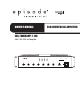
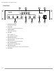
ECA COMMERCIAL AMPLIFIER OWNER’S MANUAL ECA-70MIXAMP-1-120 100V / 70V / 50V / 4Ω Amplifier 8 2 0 4 7 0 MIC 4 6 4 7 10 9 ON ON ON ON OFF OFF OFF 0 9 0 CHIME VOLUME PHANTOM MIC OFF ON PHANTOM MIC +48V OFF ON PHANTOM MIC +48V OFF ON 10 -12 +12 -12 PRE OUT INPUTS +12 7 9 Mixer Amplifier PRE OUT OFF MIC 1 MIC 2 1 2 3 MIC 3 1 2 POWER OUT Class 2 Wiring CHIME ON 3 GAIN 2 3 GAIN SOURCE 4 MIC 4 1 SOURCE 3 SOURCE 2 SOURCE 1 REC PRE OUT 1 3 GAIN GAIN
ECA-70MIXAMP-1-120 Installation Manual Important Safety Instructions WARNING: To reduce the risk of fire or electric shock, do not expose this apparatus to rain or moisture. 1. Read and follow all instructions and warnings in this manual. Keep for future reference. 2. Do not use this apparatus near water. 3. Clean only with a dry cloth. 4. Do not block any ventilation openings. Install according to manufacturer’s instructions. 5.
ECA-70MIXAMP-1-120 Installation Manual Table of Contents Important Safety Instructions ...................................................................................................................................................................... 3 Overview ........................................................................................................................................................................................................ 5 Important Instructions and Considerations .
ECA-70MIXAMP-1-120 Installation Manual Overview Episode® is one of the most highly-regarded brands of amplifiers available today. We appreciate your business and we stand committed to providing our customers with the highest degree of quality and service in the industry. The Episode® ECA-70MIXAMP-1-120 Commercial Amplifier Mixer is a superb choice for a variety of commercial applications requiring paging and multi-source background music.
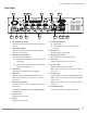
ECA-70MIXAMP-1-120 Installation Manual Front Panel 1 5 2 6 1. Source Selection Buttons Direct Selection of sources. 2. Source LEDs Indicates active signal from appropriate source. 3. Output Level Meter Master volume output level. 4. Power LED BLUE – Amplifier is On RED – Amplifier is in Protection 5. Microphone Gain Controls Independent gain for the appropriate microphone. 6. Source Gain Control Gain for all sources connected to the amplifier. 7.
ECA-70MIXAMP-1-120 Installation Manual Rear Panel 1 7 2 8 9 3 10 4 11 1. Optional 24V DC Power Input 5 6 12 13 14 15 9. Phantom Power Switches Connect to a 24V DC Power Source when lower voltage input is Off Unpowered Mic desired. On Provides phantom power to microphones with this 2. Chime Selection Switch Sets the amount of chimes heard when the Chime Trigger is activated. 2 times or 4 times. 3. Microphone Priority Dipswitch Sets mic ducking for the 4 Mic inputs.
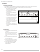
ECA-70MIXAMP-1-120 Installation Manual Installation Positioning the Amplifier Episode amplifiers are designed to help deliver a great audio experience that makes your music come alive for years to come. However, where you place the amplifier can have a large effect on the performance that you receive and the life of the unit. • Be sure that the unit is in a well-ventilated area that provides adequate cooling. • Do not block the cooling vents located on Minimum of 5" of free air space above.
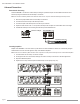
ECA-70MIXAMP-1-120 Installation Manual Standard Connections While the ECA-70MIXAMP-1-120 can be used in a variety of configurations, the diagram below shows the basic application. 2T INPUTS 4T ON +48V INPUT~120V 60Hz 160W Fuse:T6.3A L 250V INPUT~120V 60Hz 160W Fuse:T6.
ECA-70MIXAMP-1-120 Installation Manual Advanced Connections External Audio Processing The ECA-70MIXAMP-1-120 allows for external audio processing to equalize the output to suit the installed environment. This is achieved by using the unbalanced Pre Out and Amp In connections. Note: This connection is affected by Master Volume, Bass and Treble Controls., keep this in mind when calibrating the external processor. 1. Remove the jumper between the Pre Out and Amp In Connections. 2.
ECA-70MIXAMP-1-120 Installation Manual Verifying Phase When proper polarity is not maintained, the speakers play at the opposite ‘time’ from each other, or out of phase. The result is audio with lack of bass and vocals that sound thin or distant. If during or after calibrating your receiver you suspect the sound is not right and you cannot see any markings on the wire to verify polarity is correct, try this simple test: 1. Sit in the normal listening position for the system. 2.
ECA-70MIXAMP-1-120 Installation Manual Specifications Rated Power Output 120 watts 4 Microphone Inputs XLR balanced with phantom power Sensitivity -50/-2 dB 2.5/500 MV Signal To Noise Ratio >68 dB Frequency Response 40/17.
ECA-70MIXAMP-1-120 Installation Manual Troubleshooting • Power cable to the amplifier is incorrectly connected or plugged into an outlet that does not have power. Check connections and verify power on the outlet. • Audio cable to the source component is not connected properly, input or the cable is defective. Check connections or replace cable with one that has been verified as good. • Audio cable to the source component is not connected properly or the cable is defective.
ECA-70MIXAMP-1-120 Installation Manual Warranty 5-Year Limited Warranty Episode® Amplifier Products have a 5-Year Limited Warranty. This warranty includes parts and labor repairs on all components found to be defective in material or workmanship under normal conditions of use. This warranty shall not apply to products which have been abused, modified or disassembled.
121019-1253 © 2012 Episode®