
Manual


EA-AMP-12D-45A Installation Manual
Pg. 13
www.snapav.com Support: 866.838.5052
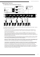
6.4. Amplier Power Control
6.4.1. Master Power Switch
The master power toggle switch at the back of the unit controls the main power. If this is turned off the amplier
will not respond to any control method. This switch should be left in the ON position after installation and setup is
nished unless the amplier will not be used for an extended period of time or is being serviced. For everyday use,
decide on one of the options below.
Use the Power Mode switch (below the Master Power switch) to select the desired power control mode.
6.4.2. Front Panel Power Button
When the amplier is powered on, the power button will illuminate solid blue and the channel LEDs should
all illuminate solid blue (if any channel LED illuminates RED, remove power immediately and consult the
Troubleshooting section to diagnose the issue. This indicates that a channel is in safe mode.). When it is off the
power button will be red and the channel LEDs will turn off.
Note: The front panel Power button only controls the amplier when the power mode is set to Power ON.
6.4.3. Power ON Mode
For manual control of the amplier power state, set the Power Mode switch to POWER On. Press the front panel
Power button to toggle between Stand-by and On.
6.4.5. AUTO (Audio Sense)
Setting the Power Mode switch to AUTO will allow the amplier to monitor the level of signal coming in from the
source connection and power on when the level is high enough to be process as an audio signal. No further setup
is needed.
When a source attached to any input generates a signal, the amplier will power on, and will remain on as long
as the signal is maintained. After 20 minutes of inactivity on all inputs, the amplier will power down and return to
Stand-by mode until a signal is received again.
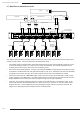
6.4.4. 12 Volt Trigger
Some audio sources and custom remote control systems can use a 12V DC trigger output to control the power
state of an amplier. The EA-AMP-12D-45A equipped with 12V DC trigger inputs and outputs to allow for trigger
control and daisy chaining for control of more than one amplier.
To utilize the 12V DC trigger function, set the Power Mode switch to the right (closest to the 12V trigger
connections) and attach a mono mini cable between the 12V trigger output of the controlling device and the
TRIGGER DC 12V IN port on the EA-AMP-12D-45A. Connect to other devices by connecting them to the OUT
port on the amplier with a mono-mini cable.
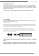
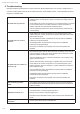
Tip
Sleeve
Cable
3.5mm Mono-mini
Tip 4.5-15V DC (constant during use)
Sleeve Ground/Common