
User guide


B-500-MTRX-230-8x8 Installation Manual
Pg. 10
© 2013 Binary
™
7.6.3. HDBaseT Outputs
FollowtheseguidelineswhenselectingandinstallingtheHDBaseTcable,andthenfollowtheinstructionsafterwardto
completetheconnectionsforanoutput.
7.6.3.1. HDBaseT Wiring Recommendations
Cable Type- Shielded or Unshielded Cat5e/6
• CableDistanceLimitations:
Cat5e/ Cat6: Upto200ft
Cat6a: Upto230ft
• UseatleastCategory5ehigh-qualitytwistedpairsolidconductorcableratedtonolessthan350Mhzbandwidth.
Thehigherthecablestandard,thebetteritwillperform.
• Forthebestresultsinstallashieldedcable.Thiswillpreventsignaldropoutandartifactsfrombeingcausedby
electromagneticandradiointerference(EMI/RFI)fromceilingfans,appliancesandelectricmotors.
• Usenomorethantwo5meterorshorter,solidorstranded,568Bterminatedpatchcablesintherun.Useshielded
patchcablesiftherunisshieldedtomaintainshieldcontinuity.
• Usenomorethantwokeystonesorcouplersintherun.Useshieldedkeystonesorcouplerswithshieldedcable
tomaintaincontinuity.
• Cleanlyterminateallcableendsandtesteverycableusedbeforeconnectingtheextendertoavoid
troubleshootingterminationproblemslater.
• MarkeachendoftheHDBaseTcablewiththeincludedlabelstoavoidconfusionlater.
Connector Type- RJ45
• UseahighqualityRJ45connectorthatmatchesorexceedsthestandardofthecableinuse.Shieldedconnectors
mustbeusedwithshieldedcables,andmustmaintaincontinuityoftheshieldtobothconnectorstoprotectfrom
interference.
• Wehighlydiscouragetheuseof“EZ”style,openendRJ45’swithHDMIextenders.
• AlwaysterminateRJ45connectorsintheHDBaseTsignalpathtothe568Bterminationstandardasrequiredby
HDBaseT standards.
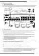
7.6.3.2. Installation Instructions
1. InstalltheCat5e/6cableandterminatetheends.Thentestthecabletoensureoperation.
2. ConnecttheHDBaseTcabletothedesiredHDBaseToutputofthematrixswitcher.
3. ConnecttheHDBaseTcabletotheB-500-RX-230-IRReceiverortheHDBaseTdeviceinuse.
4. ConnectanHDMIcable(2metersorshorterisrecommended)betweentheHDMIOUTportontheReceiverand
thedesiredHDMIinputontheDisplay.
5. AttachthepowersupplytotheReceiverandpowertheunit.
6. Installationiscomplete.Testallconnectedinputsandoutputstogethertoensurereliableoperation.
7. ForIRPass-ThroughIntegration,seesection7.8.IRPass-ThroughInstallationandSetup,page12.
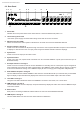
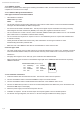
Pin 1 White/Orange Pin 5 White/Blue
Pin 2 Orange Pin 6 Green
Pin 3 White/Green Pin 7 White/Brown
Pin 4 Blue Pin 8 Brown
TIA/EIA Standard 568-B (Gold Pins Facing Up)