
Manual


B-500-MTRX-230 Installation Manual
Pg. 7
www.snapav.com Support: 866.838.5052
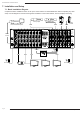
6.2. Rear Panel
1. Ethernet Port
RJ45portforconnectinganEthernetCat5e/6cableforIPcontroloftheB-500-MTRX-230.
2. System All IR Out
3.5mmmonominiport,repeatsallIRcommandsfromallconnectedHDBaseToutputs(fromIRReceiverportof
B-500-RX-230-IR).
3. System IR In
3.5mmmonominiIRinputportformatrixcontrol.
4. HDBaseT Outputs 1 through 16 (RJ45)
Connect568BterminatedCat5e/6HDBaseTcableroutedtoaB-500-RX-230-IRtofeedHDMIsignaltodisplay.
OutputsimultaneouslydisplaysthesamesourceastheHDMIoutputofthesamenumber.Oddnumberedoutputs
areatthetopandevennumberedoutputsareatthebottom.
5. HDMI Outputs 1 through 16
ConnectHDMIcablestoroutetodisplays.OutputsimultaneouslydisplaysthesamesourceastheHDBaseToutput
ofthesamenumber.Oddnumberedoutputsareatthetopandevennumberedoutputsareatthebottom.
6. Output Number Legend
Printeddiagramtoindicateoutputnumbering.
7. HDMI Inputs 1 through 8 (or 16)
ConnectHDMIcablesfromsourcestothematrixswitcherfordistribution.Oddnumberedoutputsareatthetopand
evennumberedoutputsareatthebottom.
8. IR Output to Source 1 through 8 (or 16)
Blue3.5mmmonominiportsareusedtoconnectIRashersforcontrollingsources.Theseportsmaybesetto
routecommandsonlyfromtheIRoutputcorrespondingtotheHDBaseToutputnumber(IRzonerouting),ordirectly
tothesourceselectedonanHDBaseToutput(IRsourcerouting).Oddnumberedoutputsareatthetopandeven
numberedoutputsareatthebottom.SeeSection9.1.IRSourceRoutingonpage22forroutingsetup.
9. IR Input to Room
Green3.5mmmonominiportsareusedtorouteIRcommandstotheB-500-RX-230-IRIRFlasherportconnected
toeachrespectiveoutput.Usetheseconnectionstocontroldisplaysorotherequipmentfromthematrixlocation.
Oddnumberedoutputsareatthetopandevennumberedoutputsareatthebottom.
10. Redundant Power Jacks
Dualpolarized,12VDC11.25Apowerconnections.Connectthepowersupplyonwhicheversideismoreconvenient.
11. USB Port
Reservedforfutureuse.
12. RS-232 Control (DB9)
AttachconnectionfromcontrolsystemorWindowsPCforserialcontroloftheB-500-MTRX-230.Updatermware
onthematrixswitcher.
13. USB/RS232 Toggle Switch
USBrmwareupdateswitchformainboardupdates.Must be set to RS232 for normal operation.
14. Input Number Legend
PrinteddiagramtoindicateinputandIRconnectionnumbering.
12V DC 11.2A
INPUT
IR INPUT
TO ROOM
IR INPUT
TO ROOM
IR OUTPUT
TO SOURCE
IR OUTPUT
TO SOURCE
1
2
3
4
5
6
7
8
9
10
11
12
13
14
15
16
O
1
2
3
4
5
6
7
8
9
10
11
12
13
14
15
16
UTPUTS
12V DC 11.2A
INPUT
LINK
LINK
LINK
LINK
LINK
LINK
LINK
LINK
LINK
LINK
LINK
LINK
LINK
LINK
LINK
LINK
ON
1 2 3 4 5 7
10 11 12 13
6
14
8 9
10