
Manual


B-500-MTRX-230 Installation Manual
Pg. 14
© 2013 Binary
™
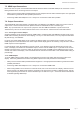
7.8. IR Pass-Through Installation and Setup
ToutilizeIRpass-throughbetweenadisplaylocationandthematrixswitcher,installaB-500-RX-230-IRatthedisplay
anduseHDBaseTforroutingthesignal.Thematrixswitcherandthematrixreceiverareequippedwithportstoallow
commandstobesenttothedisplayorfromthedisplayarea.ThissectiondetailsthepinoutsandcorrectuseoftheIR
pass-throughports.
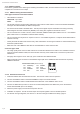
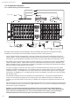
7.8.1. Matrix Switcher IR Connections
Theportsindicatedinthediagramaredescribedindetailbelow.Guidesforstandardapplicationsareincludedonthe
followingpagesforreferenceduringsetup.
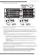
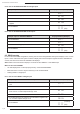
7.8.2.MatrixSwitcherIRPortConguration
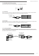
AllIRconnectionportsontheB-500-MTRX-230are3.5mmmonominiandusethispinoutconguration.Consultwith
themanufacturerofanyattachedIRequipmenttoconrmtheirpinoutmatchesbeforeuse.
1. System All IR Out
ThisportrepeatsanycommandsentfromtheIRReceiverportsonB-500-RX-230-IRMatrixReceiversconnected
to any HDBaseT output.
2. System IR In
3.5mmmonominiIRinputportformatrixswitcherIRcontrol.
3. System Input Legend
PrinteddiagramtoindicateinputandIRconnectionnumbering.
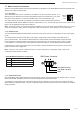
4. IR Output to Source 1 through 16
TheIRoutputfromeachconnectedB-500-RX-230-IRistransmittedtotheIROUTPUTTOSOURCEports.
Commandscanberoutedtothesourceselectedortothelike-numberedport.
5. IR Input to Room 1 through 16
Use3.5mmmini-monocablestoconnectIRasheroutputsonacontrolsystemtotheseportstosendcommands
todisplaysorequipmentlocatedattheB-500-RX-230-IRmatrixreceiverlocation.Thenumbercorrespondstothe
outputzonenumber,soIRInputtoRoomport1willsendsignalstoHDBaseToutput1.
IR Signal (Tip)
GND (Sleeve)
IR Signal Tip
GND (Ground) Ring
12V DC 11.2A
INPUT
IR INPUT
TO ROOM
IR INPUT
TO ROOM
IR OUTPUT
TO SOURCE
IR OUTPUT
TO SOURCE
1
2
3
4
5
6
7
8
9
10
11
12
13
14
15
16
O
1
2
3
4
5
6
7
8
9
10
11
12
13
14
15
16
UTPUTS
12V DC 11.2A
INPUT
LINK
LINK
LINK
LINK
LINK
LINK
LINK
LINK
LINK
LINK
LINK
LINK
LINK
LINK
LINK
LINK
ON
1 2 4 53