
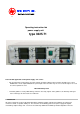
User manual

- the unit no longer works
- it has been stored for a long time under unsuitable conditions
- it has been transported under difficult conditions
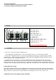
3. Controls
4. Line-up
a) The euro - connector of the power supply unit into
- Note! With longer operation with max. current consumption or in the case of short-circuit the radiator
box in the power supply unit becomes very heat. An overloading of the power pack is displayed by the red LED "
temperature rise ". At the same time by lowering the original data of the longitudinal automatic controllers of the dc
souurce against thermal overloading one protects.
Pay attention therefore absolutely to a sufficient ventilation of the power supply unit not uncover, it never the
ventilation slots at the device lower surface and at the rear wall the air outlet opening of forced cooling. Absolutely
make sure when connecting a consumer that this is not attached in the switched on status. A switched on consumer can
lead with the link to the output terminals of the power supply unit to a sparking at the connecting terminals, which again
b) Adjustable of the voltage
Turn first the adjusting knob for the current limiting a little to the right side (in the clockwise direction), until the LED (=
light emitting diode) for current limiting is not lighting. In the same instant the LED for the voltage adjustment begins to
light up. Now you can adjust the desired output voltage. The LCD display shows the adjusted output voltage.
c) Adjustment of the current limiting closing it the output
1-power switsch
2 4mm sockets source 1
3 4mm sockets source 2
4 4mm sockets source 3
5 4mm sockets source 3
6 LCD - voltage display source 1
7 LCD current display source 1
8 poti voltage source 1
9 poti current source 1
10 LED constant current operation source 1
11 LED constant current operation source 1
12 LED temperature rise source 1
13 LED output source 4
source 1 to 3 ar in the handling the same !