
User Guide

Quick-Start Guide
Product Design
Actual product may vary from photos
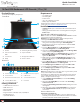
Front View
1
Handle 5 Mounting Bracket (pre installed)
2 Port Selection Buttons/
LEDs
6 Keyboard LEDs
3 Current Port 7 Display Menu Buttons
4 Rail(s) 8 Release Switch
Rear View
Package Contents
• LCD Rackmount Console x 1
• KVM Cables x 16
• M5 Cage Nuts x 8
• M5 Screws x 8
• Regional Power Cords (NA, JP, EU, UK, ANZ) x 5
• Mounting Rails x 2
• Quick-Start Guide x 1
SKU #: RKCONS1716K
16-Port VGA Rackmount LCD Console | 17 in | 1U
For the latest information, specications, and support visit www.startech.com/RKCONS1716K.
Requirements
• 1U of Rack Space
• Grounding Wire
• Power Source
• Up to 16 Computers or Servers
• Phillips Type Screwdriver
Requirements are subject to change. For the latest requirements,
please visit
www.StarTech.com/RKCONS1716K.
Installation
• Caution! Double pole / neutral fuse. Disconnect mains before
servicing.
• Always ground the unit before connecting/disconnecting the
Power Cord.
Mounting the LCD Rackmount Console
Note: It’s easier to install the LCD Rackmount Console if another
person helps you with the installation.
Warning: Use caution and proper lifting techniques when
installing the LCD Rackmount Console.
1. Based on the mounting depth of the server rack that you are
using, select the appropriate length of Mounting Rails.
2. Decide where in the server rack you want to install the LCD
Rackmount Console.
3. Insert the M5 Cage Nuts (two per Mounting Post) into the
square Mounting Holes on the Mounting Posts.
4. Align the rear Mounting Bracket Rails with the M5 Cage Nuts
on the corresponding Mounting Post.
5. Insert an M5 Screw (two per Mounting Post) through the rear
Mounting Bracket Rail and into the M5 Cage Nut. Do not
tighten the M5 Screws.
6. With assistance, slide the LCD Rackmount Console into the
server rack guiding the rear Mounting Bracket Rails into the
Rail Assembly.
7. Insert a M5 Screw (two per Mounting Post) through the front
Mounting Bracket Rail into the M5 Cage Nut.
8. Use a Phillips Type Screwdriver to tighten the M5 Screws.
9. Ensure that the rear Rails are properly aligned.
10. Use a Phillips Type Screwdriver to tighten the M5 Screws.
Grounding the LCD Console
Notes: Grounding wires are typically green or green with a yellow
stripe, and should be at least 18 AWG.
Grounding is recommended in all environments and essential in
environments with high levels of electromagnetic interference
(EMI), or frequent electrical surges.
1. Using a Phillips Head Screwdriver, loosen the Grounding
Connection Screw.
2. Attach the Grounding Wire to the shaft of the Grounding
Connection Screw.
3. Tighten the Grounding Connection Screw, making sure not to
over-tighten.
4. Attach the other end of the Grounding Wire (not connected
to the LCD Rackmount Console) to a proper earth-ground
connection.
Connect the Console
Important Considerations
• If you’re installing the Console in a closed or multi-unit rack
assembly, ensure that the environmental conditions are within
the unit’s maximum and minimum specications.
7
2
3
6
4
5
4
5
1
8
1
2
3
4
5
6
7
8
9
Manual Revision: 03/10/2022
1 Power Connection Port 6 Daisy Chain Port (not supported)
2 Power Switch 7 USB-A Ports
3 Ground Connection Screw 8 Console Monitor Port
4 Console Mouse Port 9 Host Port
5 Console Keyboard Port