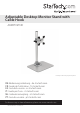
Adjustable Desktop Monitor Stand with Cable Hook ARMPIVSTND *actual product may vary from photos DE: Bedienungsanleitung - de.startech.com FR: Guide de l'utilisateur - fr.startech.com ES: Guía del usuario - es.startech.com IT: Guida per l'uso - it.startech.com NL: Gebruiksaanwijzing - nl.startech.com PT: Guia do usuário - pt.startech.com For the most up-to-date information, please visit: www.startech.
FCC Compliance Statement This equipment has been tested and found to comply with the limits for a Class B digital device, pursuant to part 15 of the FCC Rules. These limits are designed to provide reasonable protection against harmful interference in a residential installation. This equipment generates, uses and can radiate radio frequency energy and, if not installed and used in accordance with the instructions, may cause harmful interference to radio communications.
Table of Contents Introduction.............................................................................................1 Packaging Contents.................................................................................................................................. 1 Product Overview...................................................................................2 Installation...............................................................................................2 Stand Assembly...........
Introduction Packaging Contents • 1 x Instruction Manual 1 2 Aluminum Base Qty: 1 4 3 Support Post Qty: 1 6 5 Cable Clip Qty: 1 Iron Position Ring Qty: 1 8 7 Flange Qty: 1 10 Plastic Caps Qty: 4 3mm Allen Wrench Qty: 1 Instruction Manual Access Card Qty: 1 12 4mm Allen Wrench Qty: 1 14 Thumb Screws Qty: 4 M5x18mm Hex Screws Qty: 4 9 11 13 Monitor Mount Qty: 1 Torx Tool Qty: 1 15 M6x16mm Screws Qty: 2 1 Rubber Feet Qty: 4
Product Overview +45º -15º Max Note: The size and type of monitor mounted may restrict tilt motion 102mm 330mm 122mm 260mm Installation Stand Assembly 1. Attach the Aluminum Base (1) and Support Post (2) using 4 M5x18mm Hex Screws (6) and the 3mm Allen Wrench (10).
2. Attach the Rubber Feet (15) to the Base (1). 3. Slide the Cable Clip (4) onto the Support Post (2) to your desired height. Handtighten the set screw and then close the quick-release clamp to lock into place. 4. Slide the Iron Position Ring (5) onto the Cable Clip (4), with the flanges facing upward.
Warning: Ensure the Iron Position Ring is installed, and that the monitor is slid onto the Support post facing forward (over the base). The Iron Position Ring limits the ability to swivel the monitor around too far, causing the center of gravity to shift and possibly fall over. Standard LCD / LED Monitor Mounting 1. Carefully place your display face down on a protective surface to access the mounting points. 2. Attach the display to the Monitor Mount (3) using the 4 Thumb Screws (13).
3. Slide the Monitor Mount (3) onto the Support Post (2) until it rests on the Iron Position Ring (5) and tighten the set screw using the M3 Allen Wrench (15). iMac / Apple Cinema Display Mounting 1. Power off your iMac / Apple Cinema display and disconnect all cables. 2. Turn the display so the back is facing you, and tilt the display all the way forward. 3. Insert the Access Card (9) into the space directly above the stand to release the latch. Note: The access card should go into the space approx.
4. Once the latch is released, tilt the display forward another 10° to expose the 8 screws on top of the stand. The stand should lock into place. 5. When the stand is locked, hold the sides of the display and carefully place it face- down on a protective surface, with the stand hanging over the edge of your work surface. 6. Using the Torx Tool (12), remove the 8 screws that attach the stand to the back of your iMac and remove the stand.
7. Align the hole in the Flange (7) with the pin on the back of your iMac, then use the Torx Tool (12) and the screws removed in the previous step to attach the Flange. 8. Place the 4 Plastic Caps (8) onto the ends of the Monitor Mount (3). 9. Place the Monitor Mount (3) over the Flange (8) and attach using the 2 M6x16mm Screws (5) and the 4mm Allen Wrench (11). Note: Keep the Flange in the locked position while you attach the Monitor Mount.
10. Slide the Monitor Mount (3) onto the Support Post (2) until it rests on the Iron Position Ring (5) and tighten the set screw using the M3 Allen Wrench (15).
Adjusting Monitor Mount Resistance Warning: Forced movement of the Mount Bracket without loosening the screws may damage the product or the mounted displays. Always support your display from underneath when making any adjustments to the height, or the Mount Bracket to avoid damage to the display. Note: For all adjustments outlined below, turning the screw clockwise will increase the resistance, while turning the screw counter-clockwise will decrease resistance.
Specifications Weight Capacity 30.
Technical Support StarTech.com’s lifetime technical support is an integral part of our commitment to provide industry-leading solutions. If you ever need help with your product, visit www.startech.com/support and access our comprehensive selection of online tools, documentation, and downloads. For the latest drivers/software, please visit www.startech.com/downloads Warranty Information This product is backed by a ten-year warranty. In addition, StarTech.
Hard-to-find made easy. At StarTech.com, that isn’t a slogan. It’s a promise. StarTech.com is your one-stop source for every connectivity part you need. From the latest technology to legacy products — and all the parts that bridge the old and new — we can help you find the parts that connect your solutions. We make it easy to locate the parts, and we quickly deliver them wherever they need to go. Just talk to one of our tech advisors or visit our website.