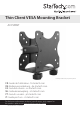
Thin Client VESA Mounting Bracket ACCSMNT *actual product may vary from photos FR: Guide de l’utilisateur - fr.startech.com DE: Bedienungsanleitung - de.startech.com ES: Guía del usuario - es.startech.com NL: Gebruiksaanwijzing - nl.startech.com PT: Guia do usuário - pt.startech.com IT: Guida per l’uso - it.startech.com For the latest information, technical specifications, and support for this product, please visit www.StarTech.com/ACCSMNT.
Use of Trademarks, Registered Trademarks, and other Protected Names and Symbols PHILLIPS® is a registered trademark of Phillips Screw Company in the United States or other countries. This manual may make reference to trademarks, registered trademarks, and other protected names and/or symbols of third-party companies not related in any way to StarTech.com. Where they occur these references are for illustrative purposes only and do not represent an endorsement of a product or service by StarTech.
Warning statements Mensagens de aviso Make sure that you assemble this product according to the instructions. Certifique-se de que monta este produto de acordo com as instruções. Never operate this product if parts are missing or damaged. Nunca opere este produto se faltarem peças ou estas estiverem danificadas. When you assemble this product, do not over-tighten the screws. Quando montar este produto, não aperte demasiado os parafusos.
Table of Contents Warnings....................................................................................................................................................... i Product dimensions................................................................................1 Product diagram.....................................................................................2 Package contents....................................................................................3 Introduction...............
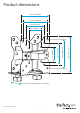
Product dimensions 4.6 in. (118 mm) 3.9 in. (100 mm) 2.9 in. (75 mm) min 0.7 in. (17 mm) to max 2.7 in. (70 mm) Instruction manual 1 5.1 in. (129 mm) 3.9 in. (100 mm) 2.9 in. (75 mm) 2 in. (50 mm) 2 in.
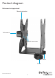
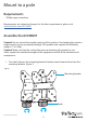
Product diagram Pole mount setup pictured Mounting bracket Pole mount M5x25 mm screws Knob Knob Instruction manual 2
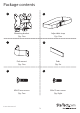
Package contents 1 2 Mounting bracket Adjustable strap Qty: One Qty: One 3 4 Pole mount Pads Qty: One Qty: Six 5 6 M5x25 mm screws M4x12 mm screws Qty: Two Qty: Eight Instruction manual 3
7 8 M4 nuts Screws Qty: Four Qty: Four 9 10 Washers Instruction manual Qty: Four Qty: One Introduction The ACCSMNT is compatible with 75x75 and 100x100 VESA monitor mount configurations. You can mount the ACCSMNT to a pole, to a VESA monitor mount, or under a desk or table. Select the mounting option that works best for your setup and follow the corresponding instructions to assemble and mount the ACCSMNT. The ACCSMNT can be mounted to a pole that is approximately 30 mm in diameter.
Mount to a pole Requirements • Phillips type screwdriver Requirements are subject to change. For the latest requirements, please visit www.StarTech.com/ACCSMNT. Assemble the ACCSMNT Caution! Do not exceed the weight capacity of this product. Overloading this product might result in injury or property damage. This product can support the following weight: 11 lb. (5 kg).
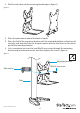
2. Pull the two halves of the mounting bracket apart. (figure 2) figure 2 3. Place the pole mount around the back of a pole. 4. Place the half of the mounting bracket with the extended platform at the front of the pole, and align the holes on the pole mount with the two holes on the raised part of the mounting bracket. 5. Use a screwdriver to insert the two M5x25 mm screws through the mounting bracket and into the pole mount, and then tighten the screws.
6. Remove the adhesive backing from one of the pads and stick it to the raised platform on the half of the mounting bracket with the extended platform. If necessary, attach additional pads in the same location to accommodate the size or shape of the equipment that you’re mounting. (figure 4) figure 4 Pad Mounting bracket 7. Stick two of the pads to the other half of the mounting bracket. If necessary, attach additional pads to accommodate the size or shape of the equipment that you’re mounting.
8. Insert the mounting bracket into the slots on the other half of the mounting bracket. (figure 6) figure 6 Mounting bracket 9. Thread the knobs onto the bolts on the bottom of the mounting bracket. Do not tighten the knobs at this point in the assembly.
10. Carefully slide your equipment onto the mounting bracket. (figure 8) figure 8 Equipment Mounting bracket 11. Slide the mounting bracket until it’s positioned tight against the equipment. 12. Tighten the knobs on the bottom of the mounting bracket. 13. Place the adjustable strap around the mounting bracket, and adjust the strap so that it fits tightly around the equipment.
Mount under a desk or table Requirements • Phillips type screwdriver Note: The provided mounting hardware may not be appropriate for the mounting surface that you’re using. If that is the case, you will need to use different mounting hardware than what was provided. Requirements are subject to change. For the latest requirements, please visit www.StarTech.com/ACCSMNT. Assemble the ACCSMNT Caution! Do not exceed the weight capacity of this product.
2. Pull the two halves of the mounting bracket apart. (figure 11) figure 11 3. Remove the adhesive backing from one of the pads and stick the pad to the raised platform on the half of the mounting bracket with the extended platform. If necessary, attach additional pads in the same location to accommodate the size or shape of the equipment that you’re mounting.
4. Stick two of the pads to the other half of the mounting bracket. If necessary, attach additional pads to accommodate the size or shape of the equipment that you’re mounting. (figure 13) figure 13 Pad Mounting bracket Assembly hole 5. Use the four mounting holes in the half of the mounting bracket with the extended platform as a template and mark the place under the desk or table where you intend to mount the ACCSMNT.
6. Position the adjustable strap behind the half of the mounting bracket with the extended platform and line up the holes on the mounting bracket with the marks that you made in the previous step. 7. Use a screwdriver to insert the screws through the mounting bracket and into the desk or table, and then tighten the screws. (figure 15) figure 15 Adjustable strap Screws 8. Insert the mounting bracket into the slots on the other half of the mounting bracket.
9. Thread the knobs onto the bolts on the bottom of the mounting bracket. Do not tighten the knobs at this point in the assembly. (figure 17) figure 17 Knob Mounting bracket 10. Carefully slide your equipment onto the mounting bracket.
11. Slide the mounting bracket until it’s positioned tight against the equipment. 12. Tighten the knobs on the mounting bracket. 13. Adjust the adjustable strap so that it fits tightly around the mounted equipment.
Mount to a VESA monitor mount Requirements • Phillips type screwdriver • Wrench Requirements are subject to change. For the latest requirements, please visit www.StarTech.com/ACCSMNT. The ACCSMNT is compatible with 75x75 and 100x100 VESA monitor mount configurations. Assemble the ACCSMNT Caution! Do not exceed the weight capacity of this product. Overloading this product might result in injury or property damage. This product can support the following weight: 11 lb. (5 kg).
2. Pull the two halves of the mounting bracket apart. (figure 21) figure 21 3. Remove the adhesive backing from one of the pads and stick the pad to the raised platform on the half of the mounting bracket with the extended platform. If necessary, attach additional pads in the same location to accommodate the size or shape of the equipment that you’re mounting.
4. Stick two of the pads to the other half of the mounting bracket. If necessary, attach additional pads to accommodate the size or shape of the equipment that you’re mounting. (figure 23) figure 23 Pad Mounting bracket Assembly hole 5. Place the half of the mounting bracket with the shorter platform over the VESA monitor mount so that the holes on the bracket line up with the holes on the mount. 6. Insert the four M4x12 mm screws through the mounting bracket and the VESA monitor mount. 7.
10. Place the adjustable strap in the recessed area on the half of the mounting bracket with the extended platform, and line up the mounting holes on the mounting bracket with the mounting holes on the back of your monitor. 11. Insert the M4x12 mm screws through the mounting bracket and into the monitor. 12. Insert the bolts on the mounting bracket into the slots on the mounting bracket and monitor assembly. 13. Thread the knobs onto the bolts on the bottom of the mounting bracket.
15. Adjust the knobs on the mounting bracket. 16. Place the adjustable strap around the equipment and the mounting bracket, and adjust the strap so that it fits tightly around the mounted equipment.
Technical support StarTech.com’s lifetime technical support is an integral part of our commitment to provide industry-leading solutions. If you ever need help with your product, visit www.startech.com/support and access our comprehensive selection of online tools, documentation, and downloads. For the latest drivers/software, please visit www.startech.com/downloads Warranty information This product is backed by a five-year warranty. StarTech.
Hard-to-find made easy. At StarTech.com, that isn’t a slogan. It’s a promise. StarTech.com is your one-stop source for every connectivity part you need. From the latest technology to legacy products — and all the parts that bridge the old and new — we can help you find the parts that connect your solutions. We make it easy to locate the parts, and we quickly deliver them wherever they need to go. Just talk to one of our tech advisors or visit our website.