
Instruction manual


USB221EXT Instruction Manual
7
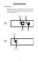
the Local unit to the Remote unit. The UTP cabling must have a
straight-through conductor configuration with no crossovers, and
must be terminated with 8-conductor RJ45 connectors at both ends.
With Surface Cabling
1. Plug one end of the Category 5 UTP cabling (not included) into the
Link port on the Local unit.
2. Plug the other end of the Category 5 UTP cabling into the Link port
on the Remote unit.
With Premise Cabling
1. Plug one end of a Category 5 patch cord (not included) into the
Link port on the Local unit.
2. Plug the other end of the patch cord into the Category 5 information
outlet near the host computer.
3. Plug one end of the second Category 5 patch cord (not included)
into the Link port on the Remote unit.
4. Plug the other end of the second patch cord into the Category 5
information outlet near the USB device.
NOTE
: The maximum length of the Category 5 UTP cable, including patch
cords, must not exceed 165 feet (50 meters).
Checking the Installation
1. Check that the Power LEDs on the Local unit and Remote unit are
both on.
2. Check that the Link LEDs on the Local unit and Remote unit are
both on.
3. Check that the Host LED on the Local unit is on.
4. On the host PC, open the Device Manager applet. Expand the entry
for Universal Serial Bus controllers by clicking the + sign. If the
USB221EXT has been installed correctly you should find it listed
as a Generic USB Hub.