
Instruction manual


Instruction Manual
3
LED Indicators
Link OK / Power
Console Unit
Solid Red: Power on
Computer Unit
Solid Green: Power on
Both Units
Solid Blue: Connection to a powered-on
extender unit detected
Status LED Flashing Yellow: Link / Activity indicator
Installation
Hardware Installation
Preparing Your Site
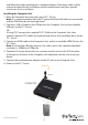
1. Determine the locations for your source PC / Server you are extending, and the
remote console.
2. Prepare SC to SC ber optic cabling (50/125 or 62.5/125) at the required distance
for interconnection between Console Unit and Computer Unit. See the chart below
for cabling considerations.
Cable Type Multi-Mode Single Mode
Cable Diameter 50/125µm 62.5/125µm 9/125µm
Video
Resolution
1080p 1080i 1080p 1080i 1080p 1080i
Max. Cable
Length
1000m
(3281ft)
1200m
(3937ft)
450m
(1476ft)
550m
(1804ft)
1000m
(3281ft)
1200m
(3937ft)
• OM3 ber optic cable is recommended.
• It is recommended to complete the ber cable installation in one pull where
possible.
• The cable used should not exceed the Max. Cable Length (refer to the table above),
otherwise signal degradation may occur.
• Order the appropriate cable lengths, conforming to your application environment