
Owners manual


Instruction Manual
4
Hardware Guide
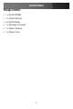
Front Panel
1. Power Supply Connects to a DC 12V power adapter.
2. HDB15 Connector Connect to the console monitor.
3. USB Type A Connectors Connect to the console keyboard and
mouse ports.
4. Port LED Indicator Displays the status of connected PCs (for
more specific instructions, see the table
below).
5. Setup Button Press this button to bring up the IP-OSD
menu.
6. RJ-45 Connector Connects to the LAN.
7. RS-232 Connector Connects to a PC for initial setup.
8. Reset Button This dual-function button selects Power
Reset or Restore Factory Defaults.
9. Auxiliary Input Link - Reserved for multimedia module.
1
2
3
4
5
6
7
8
9
LED Color Meaning
Green
Connected to a PC that is powered on.
Red
Port selected.
Blue
Data-transfer function is enabled.