SAT3540ER2 Instruction Manual SATA Hard Drive Enclosure 3.5” 4 Drive eSATA RAID External Hard Drive Enclosure with Controller Card Manual Revision:06/28/2010 For the most up-to-date information, please visit www.startech.
FCC Compliance Statement This equipment has been tested and found to comply with the limits for a Class B digital device, pursuant to part 15 of the FCC Rules. These limits are designed to provide reasonable protection against harmful interference in a residential installation. This equipment generates, uses and can radiate radio frequency energy and, if not installed and used in accordance with the instructions, may cause harmful interference to radio communications.
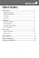
Table of Contents Introduction...................................................................... 1 Packaging Contents.....................................................................1 System Requirements..................................................................1 Front View.....................................................................................2 Rear View.....................................................................................2 Installation...........................
Introduction The SAT3540ER2 delivers a high performance external RAID solution that lets you install up to four SATA hard drives for connection to the host computer through eSATA. With support for up to four 2TB SATA hard drives, the enclosure features individual removable drive trays that make hot swapping or interchanging failed or extra hard drives easy.
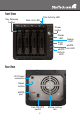
Front View Disk Activity LED Tray Release button Disk Link LED Power button Power LED Error LED Ready LED eSATA eSATA Link LED Activity LED Rear View DC Power connector Reset button eSATA port Fan ON/OFF switch 2 80mm cooling fan
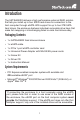
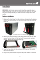
Installation WARNING: Hard drives require careful handling, especially when being transported. If you are not careful with your hard disk, lost data may result. Always handle your hard drive and storage device with caution. Enclosure Installation 1. Remove the drive trays from the enclosure, by pressing the release button, then pushing down on the arms to eject them and slide the trays out. *installation photos are for reference only 2.
Driver Installation No driver installation is required for these operating systems, as this hard drive enclosure is natively supported, so the drivers are already installed. Controller Card Installation WARNING! PCI Express cards, like all computer equipment, can be severely damaged by static electricity. Be sure that you are properly grounded before opening your computer case or touching your PCI Express card. StarTech.
Driver Installation Windows 2000/XP/Server 2003 1. When the Found New Hardware wizard appears on the screen, insert the Driver CD into your CD/DVD drive. If you are prompted to connect to Windows Update, please select the “No, not this time” option and click Next. 2. Select the option “Install Drivers Automatically (Recommended)” and then click the Next button. 3. Windows should now start searching for the drivers. Once this has completed, click the Finish button. Windows Vista/7 1.
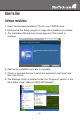
How to Use Software Installation 1. Insert the included installation CD into your CD/DVD drive. 2. Double-click the Setup program to begin the installation procedure. 3. The Installation Wizard start screen appears. Click Install to continue. 4. Wait for the installation process to complete. 5. Check or uncheck the box “Launch the application right now” and then click Finish. 6. The Manager Utility is installed under the “Programs” section of the Start Menu under “JMicron HW RAID Manager”.
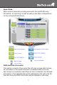
Basic Mode Basic mode is aimed at providing users with disk and RAID array information, an event log, as well as perform the basic configurations on the connected hard drives. RAID and Disk Information This section consists of two parts. The left side is a tree which shows all controllers on the system and their connected RAID units and hard drives in a hierarchy view. When an item is selected, the detailed information of the selected item will be displayed on the right side.
Controller Information If a Controller item is selected from the tree view, it will display the model name and capacity of any RAID units and hard drives connected to the controller. For RAID member disks, the hard drive charts on the right side will be shown with different colors according to the different RAID level.
Event Log Viewer The RAID Manager will monitor the status of all connected hard drives and RAID units and keep records of the occurrence of events. All events can be viewed through this event log viewer page. Logs can be saved to a profile by pressing the “Save to Profile” button or cleared by pressing the “Clear” button. Basic RAID Configuration Basic RAID configurations for the connected hard drives can be setup from here.
press the “Apply” button to confirm the configuration or press the “Cancel” button to restore to the original configuration. After the user confirms to apply the configuration, it will pop up another progress window to show the configuration status. After the RAID configuration finishes, it will pop up a message dialog to tell that a RAID is newly created or a RAID has been deleted. The disk charts on the right side will be redrawn to reflect the result of the new configuration.
any remaining hard drives. The RAID array size can be modified by simply clicking the specified disk chart and adjusting the disk size with the slider at the bottom. The RAID array can be deleted by checking the “Delete RAID” check box. If the deleted RAID array is password protected, the password prompt will automatically open. Click the “Apply” button once all configuration settings are done.
RAID Levels Clone (RAID 1 + Spare) Creates a standard RAID 1 mirrored array, and then uses an extra hard drive as a spare, in case of failure of one of the disks in the RAID 1. Span (Concatenation) Spanning concatenates (joins) multiple hard drives into a single large disk. Provides no performance or redundancy benefits. RAID 0 (Stripe) Striping combines multiple disk into a single large disk array. The data is split evenly across each disk simultaneously.
Specifications Bus Interface SATA 3.0Gb/s Number of Drive Bays 4 Enclosure: JMicron JMB393 Chipset ID Controller Card: Silicon Image SiI3531 External Connectors 1 x eSATA* LEDs Power, Ready, Error, eSATA Link, eSATA Activity 4 x Hard Drive Link 4 x Hard Drive Activity Cooling Fan 1 x 80mm Maximum Data Transfer Rate eSATA: 3.0Gb/s Supported RAID Modes RAID 0, 1, 5, 1+0, JBOD (single), Spanning, Clone (RAID 1 + Spare) Hard Drive Compatibility 3.5” SATA 1.5/3.
Technical Support StarTech.com’s lifetime technical support is an integral part of our commitment to provide industry-leading solutions. If you ever need help with your product, visit www.startech.com/support and access our comprehensive selection of online tools, documentation, and downloads. Warranty Information This product is backed by a one year warranty. In addition, StarTech.
StarTech.com has been making “hard-to-find easy” since 1985, providing high quality solutions to a diverse IT and A/V customer base that spans many channels, including government, education and industrial facilities to name just a few. We offer an unmatched selection of computer parts, cables, A/V products, KVM and Server Management solutions, serving a worldwide market through our locations in the United States, Canada, the United Kingdom and Taiwan. Visit www.startech.