
Instruction manual

Instruction Manual
3
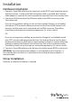
Installation
Hardware Installation
1. Connect a 9-pin DB9 cable from the Local unit, to the RS232 serial connector on the
local/host device. A male/male DB9 null modem cable is provided, but if another
cable/adapter is required, this can be purchased separately from www.startech.com.
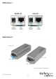
2. Connect an RJ45 terminated Cat5 Ethernet cable to the RJ45 connector on the
Transmitter unit.
If you are using surface cabling, ensure you have enough Category 5 unshielded
twisted pair (UTP) network cabling to connect the Host Unit to the Remote Unit’s
location, and that each end is terminated with an RJ45 connector. The cabling
should not go through any networking equipment (i.e. router, switch).
OR
If you are using premises cabling, ensure that the Category 5 unshielded twisted
pair (UTP) network cabling between the Host Unit and the Remote Unit has been
properly terminated in a wall outlet in each location and there is a patch cable long
enough to connect the Remote Unit and the Host Unit to their respective outlets.
The cabling should not go through any networking equipment (i.e. router, switch).
3. Connect a 9-pin DB9 cable from the Remote Unit to the remote RS232 serial device.
OPTIONAL: Connecting the power adapters is not required in most situations. If
the extender does not work, or is intermittent, connecting the power adapters is
recommended.
Driver Installation
No driver or software installation is required.