
User Manual

Instruction Manual
3
Connect the cables to the output of the attached network device and then
to the input of the DIN-Rail Industrial Fiber Media Converter. Once both
devices are powered on, the installation is complete.
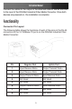
Functionality
Connector Pin Layout
The following table shows the functions of each of the pins on the RJ-45
connectors to the 10/100Base-TX ports on the DIN-Rail Industrial Fiber
Media Converter:
Pin Regular Port Uplink Port
1
Input Receive Data + Output Transmit Data +
2
Input Receive Data - Output Transmit Data -
3
Output Transmit Data + Input Receive Data +
4
Not Used Not Used
5
Not Used Not Used
6
Output Transmit Data - Input Receive Data -
7
Not Used Not Used
8
Not Used Not Used