
Manual

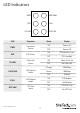


Instruction Manual
4
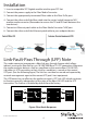
Installation
1. Insert a compatible SFP Gigabit module into the open SFP slot
2. Connect the power supply to the Fiber Media Converter
3. Connect the appropriately terminated Fiber cable to the Fiber Tx/Rx port
4. Connect the other end of the ber cable into the router/switch/computer NIC/
another media converter (Remember to reverse the TX and RX leads between the
two devices)
5. Connect an Ethernet patch cable to the Fiber Media Converter “LAN”port
6. Connect the other end of the Ethernet patch cable to your endpoint device
Link-Fault-Pass Through (LFP) Note
This media converter incorporates a ber link pass through feature which allows
indirect sensing of a ber link loss via 10/100/1000 Base‐TX UTP connection. Whenever
the media converter detects a link loss condition on the receive ber (FX LNK O),
it disables its UTP transmitter so that a link loss condition is sensed on the receive
UTP port. (See the following gure) The link loss can then be sensed and reported by
network management agent at the remote UTP port’s host equipment.
The LFP feature has no eect on the media converter’s UTP Link LED, which continues
to function normally, independent of the state of the ber LNK LED and the UTP
transmitter. This feature is disabled by default from the factory.
UTP UTP
Link Link
Fiber
Remote Fault
Switch
or PC
Switch
or PC
TX (OFF)
RX (OFF)
Figure: Fiber Break Responses
Fail Fail
TX
RX
TX RX
RX TX