Enhanced Console Server ECS0016
FCC Compliance Statement This equipment has been tested and found to comply with the limits for a Class B digital device, pursuant to part 15 of the FCC Rules. These limits are designed to provide reasonable protection against harmful interference in a residential installation. This equipment generates, uses and can radiate radio frequency energy and, if not installed and used in accordance with the instructions, may cause harmful interference to radio communications.
Instruction Manual Table of Contents Introduction..................................................................................... 1 Features.......................................................................................1 Package Contents........................................................................1 Initial Configuration........................................................................ 2 Power Connection........................................................................
Instruction Manual Serial Port and Network Host Configuration............................... 13 Configuring Serial Ports...............................................................13 Common Settings.........................................................................15 Console Server Mode...................................................................16 SDT Mode....................................................................................20 Power Strip Mode...................................
Instruction Manual Setting up MetaConnect for Remote Desktop access . ...............61 Set up MetaConnect Serial Ports on ECS0016 . .........................62 SSH port forward over the ECS0016 Serial Port..........................63 Alerts and Logging......................................................................... 64 Enable SMTP, SNMP and/or Nagios............................................64 Configure Alerts............................................................................
Instruction Manual Status Reports................................................................................ 85 Port Access and Active Users......................................................85 Statistics.......................................................................................86 Support Reports...........................................................................86 Syslog...........................................................................................
Instruction Manual Raw Access to Serial Ports..........................................................110 Access to Serial Ports..................................................................110 Accessing the Console Port.........................................................110 IP - Filtering..................................................................................111 Customizing the IP-Filter:.............................................................112 Modifying SNMP Configuration.......
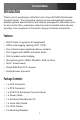
Instruction Manual Introduction Thank you for purchasing a StarTech.com Conyx ECS0016 Enhanced Console Server. This innovative remote service management solution enables system administrators and network managers to affordably monitor and control their computers, networks and connected serial devices remotely, from anywhere in the world (using an Internet connection).
Instruction Manual Initial Configuration Unpack the ECS0016 kit and verify you have all of the parts indicated in the Package Contents list shown on the previous page, and that they all appear in good working order. If you are installing your ECS0016 in a rack, you will need to attach the rack-mounting brackets supplied with the unit, and install the unit in the rack.
Instruction Manual Management Console Connection The ECS0016 is pre-configured with a default IP Address: 192.168.0.1 and Subnet Mask: 255.255.255.0 . Directly connect a PC or workstation to the ECS0016. To configure the ECS0016 with a browser, the connected PC or workstation should have an IP address in the same range as the ECS0016 (e.g. 192.168.0.100) Please note: For initial configuration, it is recommended that the ECS0016 be connected directly to a single PC or workstation.
Instruction Manual ARPPing IP Address Assignment If it is not convenient to change the PC/workstation network address, you can use the ARP-Ping command to reset the ECS0016 IP address. To do this from a Windows PC: 1. Click Start > Run 2. Type cmd in the text box provided and click OK to open the command line 3. Type arp –d to flush the ARP cache: 4. Type arp –a to view the current ARP cache which should now be empty.
Instruction Manual You will be prompted to log in. Enter the default administration username and administration password: Username: root Password: default Please note: The ECS0016 is factory configured with HTTP disabled and HTTPS enabled appliances Please note: Note If you are not able to connect to the Management Console at 192.168.0.
Instruction Manual Administrator Password For security reasons, only the Administrator (the administration user named root) can initially log into your gateway; only those people who know the root password can access and reconfigure the ECS0016 gateway itself. As such, it is important that you enter and confirm a new password before giving the ECS0016 any access to, or control of, your computers and network appliances. To do so: 1. Select System: Administration 2.
Instruction Manual Network IP address You now must enter an IP address for the principal Ethernet (LAN/Network/Network1) port on the ECS0016 gateway, or enable its DHCP client so that it automatically obtains an IP address from a DHCP server on the network to which it is connected. On the System: IP menu: 1. Select the Network page then check DHCP or Static for the Configuration Method 2. If you selected Static you must manually enter the new IP Address, Subnet Mask, Gateway and DNS server details.
Instruction Manual By default the ECS0016 LAN port auto detects the Ethernet connection speed. However you can use the Media menu to lock the Ethernet to 10 Mb/s or 100Mb/s and to Full Duplex (FD) or Half Duplex (HD). Please note: If you have changed the ECS0016 IP address, you may need to reconfigure your PC/workstation so it has an IP address that is in the same network range as this new address (as detailed in an earlier note in this chapter). 4. Click Apply.
Instruction Manual HTTPS This ensures secure browser access to all of the Management Console menus. It also allows appropriately configured Users secure browser access to selected Management Console Manage menus. If you enable HTTPS, the Administrator will be able to use a secure browser connection to the ECS0016 gateway’s Management Console. By default HTTPS is enabled, and it is recommended that only HTTPS access be used if the gateway is to be managed over any public network (e.g. the Internet).
Instruction Manual There are also a number of related service options that can be configured at this stage: SNMP This will enable netsnmp in the gateway, which will keep a remote log of all posted information. SNMP is disabled by default. To modify the default SNMP settings, the Administrator must make the edits at the command line. Ping This allows the ECS0016 to respond to incoming ICMP echo requests.
Instruction Manual Communications Software You have configured access protocols for the Administrator client to use when connecting to the ECS0016. User clients (who you may set up later) will also use these protocols when accessing ECS0016 serial attached devices and network attached hosts. You will need to have appropriate communications software tools set up on the Administrator (and User) client’s PC/workstation.
Instruction Manual MetaConnect is a Java client program that couples the SSH tunneling protocol with popular access tools such as Telnet, SSH, HTTP, HTTPS, VNC, RDP, to provide point-and-click secure remote management access to all the systems and devices being managed. MetaConnect can be installed on Windows 2000, XP, 2003, Vista™ PCs and on most Linux, UNIX and Solaris configurations PuTTY Communications packages like PuTTY can be also used to connect to the ECS0016 gateway command line.
Instruction Manual SSHTerm Another common communications package that may be useful is SSHTerm, an open source package that can be downloaded from http://sourceforge.net/projects/sshtools To use SSHTerm for an SSH terminal session from a Windows Client, you simply Select the File option and click on New Connection A new dialog box will appear for your ‘Connection Profile’ where you can type in the host name or IP address (for the ECS0016 unit) and the TCP port that the SSH session will use (port 22).
Instruction Manual Configuring Serial Ports To configure the serial port, you must first set the protocols and the RS232 parameters that are to be used for the data connection to that port (e.g. baud rate). Then you must select what mode the port is to operate in.
Instruction Manual • When you have reconfigured the common settings and the mode for each port, you set up any remote syslog, then click Apply Common Settings There are a number of common settings that can be set for each serial port, that are independent of the mode in which the port is being used.
Instruction Manual • Before proceeding with further serial port configuration, you should connect the ports to the serial devices they will be controlling, and ensure they have matching settings Please Note that the serial ports are all factory set to RS232 9600 baud, no parity, 8 data bits, 1 stop bit and Console Server Mode. The baud rate can be changed to 2400 – 230400 baud using the management console.
Instruction Manual • From Win2000/XP/NT, you can run telnet from the command prompt (cmd.
Instruction Manual SSH It is recommended that you use SSH as the protocol whereby the User or Administrator connects to the ECS0016 gateway (or connects to the attached serial consoles) over the Internet (or any other public network). This will provide authenticated SSH communications between the SSH client program on the remote user’s PC/workstation and the gateway, so the user’s communication with the serial device attached to the gateway is secure.
Instruction Manual For a User named ‘Paul’ to access serial port 2, when setting up the SSHTerm or the PuTTY SSH client, instead of typing username = paul and ssh port = 3002, the alternate is to type username = paul:port02 (or username = fred:ttyS1) and ssh port = 22.
Instruction Manual RFC2217 also enables the serial port to be tunneled to a remote ECS0016 client gateway, so two serial port devices can be transparently interconnect over a network. Accumulation Period By default, once a connection has been established for a particular serial port (such as a RFC2217 redirection or Telnet connection to a remote computer) then any incoming characters on that port are forwarded over the network on a character by character basis.
Instruction Manual Data Carrier Detect (DCD) pin on the serial device being raised. When a connection is detected, the getty program issues a login: prompt, and then invokes the login program to handle the actual system login. Serial Bridging Mode Serial bridging is the encapsulation of serial data into network packets and the transport of the data over a network. So two ECS0016 gateways can configured to act as a virtual serial cable over IP network.
Instruction Manual can also be configured to support the remote syslog protocol on a per serial port basis. • Select the Syslog Facility/Priority fields to enable logging of traffic on the selected serial port to a syslog server; and to appropriately sort and action those logged messages (i.e. redirect them/ send alert email etc.
Instruction Manual 1. Select Serial & Network: Users & Groups to display the configured Groups and Users 2. Click Add Group. 3. Add a Group name and Description for each new Group, then select Accessible Hosts and Accessible Ports to specify the serial ports and hosts you wish any Users in this new Group to be able to access. 4. Click Apply 1. Select Serial & Network: Users to display the configured Users. 2. Click Add User to add a new User. 3. Add a Username and a confirmed Password for each new User.
Instruction Manual The Administrator can also edit the Access settings for any existing Users. To do so: 1. Select Serial & Network: Users & Groups 2. Click Edit for the User to be modified. Authentication For details on authentication, please refer to the section titled Remote Authentication Configuration. Please note: There are no limits to the number of Users you can set up, or on the number of Users per serial port or host.
Instruction Manual Network Hosts To access a locally networked computer or appliance (referred to as a Host) you must identify the network connected Host, then specify the TCP or UDP ports/services that will be used to control that Host. Selecting Serial & Network: Network Hosts presents all of the network connected Hosts that have been enabled for access, as well as the related access TCP ports/services.
Instruction Manual Trusted Networks The Trusted Networks utility provides the option to select specific IP addresses at which users (Administrators and Users) must be located, in order to have access to the ECS0016 serial ports. To add an address designation: 1. Select Serial & Network: Trusted Networks. 2. To add a new trusted network, select Add Rule. 3. Select the Accessible Port(s) to which the new rule is to be applied. 4. Enter the Network Address of the subnet to be granted access. 5.
Instruction Manual Network IP Address: 204.15.5.128 Subnet Mask: 255.255.255.224 6. Click Apply. The above Trusted Networks will limit access by Users and the Administrator, to the ECS0016 serial ports and network attached hosts, however they do not restrict access by the Administrator to the ECS0016 console server itself. To change the default settings for this access, you will need to edit the IP tables rules (as described in the Advanced section).
Instruction Manual 5. Next, you must register the Public Key as an Authorized Key on the Slave. In the simple case with only one Master with multiple Slaves, you need only upload the one RSA or DSA public key for each Slave. Please note: The use of key pairs can be confusing as in many cases one file (Public Key) fulfills two roles – Public Key and Authorized Key. 6. Select System: Administration on the Slave’s Management Console. 7.
Instruction Manual The next step is to Fingerprint each new Slave-Master connection, which will authenticate you as a legitimate user for the SSH session. On the first connection the Slave will receive a fingerprint from the Master which will be used on all future connections.
Instruction Manual of clustered console servers and the connected devices) 3. Enter the full number of serial ports on the Slave unit in Number of Ports 4. Click Apply. This will establish the SSH tunnel between the Master and the new Slave The Serial & Network: Cascaded Ports menu displays all of the Slaves and the port numbers that have been allocated on the Master.
Instruction Manual next time the Master sends out a configuration file update. • Also, while the Master is in control of all Slave serial port related functions, it is not Master over the Slave network host connections or over the Slave console server system itself. • Slave functions such as IP, SMTP & SNMP Settings, Date &Time, DHCP server must be managed by accessing each Salve directly and these functions are not over written when configuration changes are propagated from the Master.
Instruction Manual Remote Power Control (RPC) The ECS0016 Management Console monitors and controls Remote Power Control devices using the embedded PowerMan open source management tool. RPCs include power distribution units (PDUs) and IPMI power devices. Serial PDUs invariably can be controlled using their command line console, so you could manage the PDU through the ECS0016 using a remote Telnet client. Also, you could use proprietary software tools supplied by the vendor.
Instruction Manual 3. Select the Serial & Network: RPC Connections menu. This will display all the RPC connections that have already been configured. 4. Click Add RPC. 5. Enter a RPC Name and Description for the RPC. 6. In “Connected Via” select the pre-configured serial port or the network host address that connects to the RPC. 7. Select any specific labels you wish to apply to specific RPC Outlets (e.g. the PDU may have 20 outlets connected to 20 powered devices you may wish to identify by name).
Instruction Manual 8. Enter the Username and Password used to login into the RPC (Note that these login credentials are not related the Users and access privileges you will have configured in Serial & Networks: Users & Groups). 9. Check Log Status and specify the Log Rate (minutes between samples) if you wish the status from this RPC to be logged. These logs can be views from the Status: RPC Status screen. 10. Click Apply.
Instruction Manual 2. Click on View Log or select the RPCLogs menu and you will be presented with a table of the history and detailed graphical information on the select RPC 3. Click Manage to query or control the individual power outlet.
Instruction Manual The outlet status is displayed and you can initiate the desired Action to be taken by selecting the appropriate icon: Power ON Power OFF Power Cycle Power Status You will only be presented with icons for those operations that are supported by the Target you have selected. Uninterruptible Power Supply Control (UPS) The ECS0016 console server can manage UPS hardware using Network UPS Tools.
Instruction Manual The console server may or may not be drawing power through the Managed UPS (see the Configure UPS powering the console server section below). When the UPS’s battery power reaches critical, the console server signals and waits for slaves to shutdown, then powers off the UPS. Serial and network connected UPSes must first be configured on the console server with the relevant serial control ports reserved for UPS usage, or the with the UPS allocated as a connected Host: 1.
Instruction Manual 4. Enter a UPS Name and Description (optional) and the select if the UPS will be Connected Via USB or over pre-configured serial port or via HTTP/HTTPS over the preconfigured network Host connection 5. Enter the UPS login details. This Username and Password is used by slaves of this UPS (i.e. other computers that are drawing power through this UPS) to connect to the console server to monitor the UPS status and shut themselves down when battery power is low.
Instruction Manual positive number, or -1. 0s are shut down first, then 1s, 2s, etc. -1s are not shut down at all. Defaults to 0 7. Select the Driver that will be used to communicate with the UPS. The drop down menu presents full selection of drivers from the latest Network UPS Tools (NUT version 2.2.0) and additional information on compatible Ups hardware can be found at http://www.networkupstools. org/compat/stable.html 8.
Instruction Manual If the ECS0016 is drawing power through a Managed UPS that has already been configured, select Local, enter the Managed UPS Name and check Enabled. The ECS0016 continues to be the master of this UPS. If the UPS that powers the console server is not a Managed UPS for that console server, then then console server can still connect to a remote NUT server (upsd) to monitor its status as a slave. In this case, select Remote, and enter the address, username and password to connect.
Instruction Manual Configuring Powered Computers to Monitor a Managed UPS Once you have added a Managed UPS, each server that is drawing power through the UPS should be setup to monitor the UPS status as a slave. This is done by installing the NUT package on each server, and setting up upsmon to connect to the ECS0016. Refer to the NUT documentation for details on how this is done, specifically sections 13.5 to 13.10. http://eu1.networkupstools.org/ doc/2.2.0/INSTALL.html An example upsmon.
Instruction Manual - username is the Username of the Managed UPS - password is the Password of the Manager UPS UPS Alerts You can now set UPS alerts using Alerts & Logging: Alerts UPS Status You can monitor the current status of all of your network, serially or USB connected Managed UPSes or any Monitored UPS 1. Select the Status: UPS Status menu and a table with the summary status of all connected UPS hardware will be displayed 2.
Instruction Manual 4. Select UPS Logs and you will be presented with the log table of the load, battery charge level. temperature and other status information from all the Managed and Monitored UPS systems. This information will be logged for all UPSes which were configured with Log Status checked.
Instruction Manual NUT is built on a networked model with a layered scheme of drivers, server and clients. 1. The driver programs talk directly to the UPS equipment and run on the same host as the NUT network server upsd. Drivers are provided for a wide assortment of equipment from most of the popular UPS vendors and they understand the specific language of each UPS and map it back to a compatibility layer.
Instruction Manual status of a UPS, writing it to a file. All these clients all run on the ECS0016 (for Management Console presentations) but they also are run remotely (on locally powered servers and remote monitoring systems). This layered NUT architecture enables: • Multiple manufacturer support: NUT can monitor USB models from 79 different manufacturers with a unified interface • Multiple architecture support: NUT can manage serial and USB connected models with the same common interface.
Instruction Manual Using the Management Console, Administrators can view the ambient temperature and humidity and set the EMD to automatically send alarms progressively from warning levels to critical alerts. Connecting the EMD The Environmental Monitor Device (EMD) connects to any serial port on the console server via a special EMD Adapter and standard CAT5 cable. The EMD is powered over this serial connection and communicates using a custom handshake protocol.
Instruction Manual 2. Screw the bare wires on any smoke detector, water detector, vibration sensor, open-door sensor or general purpose open/close status sensors into the terminals on the EMD The EMD can be used only with an ECS0016 and cannot be connected to standard RS232 serial ports on other appliances. 1. Select Environmental as the Device Type in the Serial & Network: Serial Port menu for the port to which the EMD is to be attached. No particular Common Settings are required. 2. Click Apply. 3.
Instruction Manual 5. Enter a Name and Description for the EMD and select pre-configured serial port that the EMD will be “Connected Via”. 6. Provide Labels for each of the two alarms 7. Check Log Status and specify the Log Rate (minutes between samples) if you wish the status from this EMD to be logged. These logs can be views from the Status: Environmental Status screen 8.
Instruction Manual Environmental Status You can monitor the current status of all of EMDs and their probes 1. Select the Status: Environmental Status menu and a table with the summary status of all connected EMD hardware will be displayed 2.
Instruction Manual Failover and Out-of-Band Dial Access The ECS0016 has a number of failover and out-of-band access capabilities to ensure high availability.
Instruction Manual Please note: The ECS0016 requires an external modem attached (via a serial cable) to the DB9 port (marked Local, located on the front panel). Configure Dial In PPP To enable dial-in PPP access on the ECS0016 console/modem port: 1. Select the System: Dial menu option and the port to be configured (Serial DB9 Port or Internal Modem Port).
Instruction Manual 6. Select the Authentication Type to be applied to the dial-in connection. • The ECS0016 uses authentication to challenge Administrators who dial-in to the gateway. (For dial-in access, the username and pass word received from the dial-in client are verified against the local authentication database stored on the ECS0016). The Administrator must also have their client PC / workstation configured to use the selected authentication scheme. 7.
Instruction Manual ECS0016 gateways also support dial-back for additional security. Check the Enable Dial Back box and enter the phone number to be called to reestablish an OoB link, once a dial-in connection has been logged. Using The MetaConnect client Administrators can use the MetaConnect Java client software to set up secure OoB dial-in access to remote ECS0016 gateways. OoB access uses a different path for connecting to the gateway than that which is used for regular data traffic.
Instruction Manual Similarly for Windows® 98, you double-click My Computer on the Desktop, then open Dial-Up Networking and double-click Make New Connection and proceed as outlined for Windows XP (see previous section). Set up Linux clients The online tutorial http://www.yolinux.com/TUTORIALS/LinuxTutorialPPP.
Instruction Manual • Command line PPP and manual configuration (which works with any Linux distribution) • Using the Linuxconf configuration tool (for Red Hat compatible distributions). This configures the scripts ifup/ifdown to start and stop a PPP connection • Using the Gnome control panel configuration tool • WVDIAL and the Redhat “Dialup configuration tool” • GUI dial program Xisp.
Instruction Manual Secure Tunneling & MetaConnect Serial access to Linux consoles, Windows EMS/BIOS etc. Control serial connected firewalls, power switches and other devices MetaConnect establishes secure tunnel to gateway, then Telnet/SSH connection to serially attached devices Remote or Local User/ Administrator Telnet or SSH connection to serially attached devices MetaConnect can also be used to access text consoles on devices that are attached to the ECS0016 gateway serial ports.
Instruction Manual then Close and Close again 3. Assuming you have already set up the target ECS0016 as a gateway in your MetaConnect client (with username/ password etc), select this gateway and click the Host icon to create a host (alternatively, select File > New Host). 4. Enter 127.0.0.1 as the Host Address and select Serial Port 2 for Service. In Descriptive Name, enter as appropriate (e.g. Loop back ports, Local serial ports, etc.). Click OK to continue.
Instruction Manual 1. Select Users & Groups from Serial & Network. 2. Click Add User. 3. Enter a Username, Description and Password/Confirm. 4. Select 127.0.0.1 from Accessible Host(s) and select Port 2 from Accessible Port(s). 5. Click Apply. MetaConnect for OoB Connection to the Gateway MetaConnect can also be set up to connect to the gateway out-of-band (OoB). OoB access uses a different path for connecting to the gateway than that which is used for regular data traffic.
Instruction Manual • To initiate a pre-configured dialup connection under Windows, use the following Start Command: cmd /c start “Starting Out of Band Connection” /wait /min rasdial network_connection login password (where network_connection is the name of the network connection as displayed in Control Panel -> Network Connections, login is the dial-in username, and password is the dial-in password for the connection) • To initiate a pre-configured dialup connection under Linux, use the following
Instruction Manual To make the OoB connection using MetaConnect: Select the gateway from the left hand list of gateways and hosts. Under Gateway Actions in the right hand pane, click Out Of Band. The status bar will change color to indicate this gateway is now being accessed using the OoB link, rather than the primary link. When you connect to a service on a host behind the gateway, or the gateway itself, MetaConnect will initiate the OoB connection using the provided Start Command.
Instruction Manual PuTTYgen: http://www.chiark.greenend.org.uk/~sgtatham/putty/download.html OpenSSH: http://www.openssh.org/ OpenSSH (Windows): http://sshwindows.sourceforge.net/download/ • Upload the public part of your SSH key pair (this file is typically named id_rsa.pub or id_dsa.pub) to the SSH gateway, or otherwise add to .ssh/authorized keys in your home directory on the SSH gateway. • Next, add the private part of your SSH key pair (this file is typically named id_rsa or id_dsa) to MetaConnect.
Instruction Manual system, reboot the machine etc. ECS0016’s Secure Tunneling uses SSH tunneling, so this RDP traffic is securely transferred through an authenticated and encrypted tunnel. MetaConnect with RDP also allows remote Users to connect to Windows XP, Windows 2003 computers and to Windows 2000 Terminal Servers, and to have access to all of the applications, files, and network resources (with full graphical interface just as though they were in front of the computer screen at work).
Instruction Manual ration protocols on that port Note: If you leave the Username and User Password fields blank, they default to portXX and portXX where XX is the serial port number. The default username and password for Secure RDP over Port 2 is port02 • Ensure the ECS0016 Common Settings (Baud Rate, Flow Control) are the same as were set up on the Windows computer COM port and click Apply • RDP and VNC forwarding over serial ports is enabled on a Port basis.
Instruction Manual Alerts and Logging This chapter describes the logging and alert generation features of the console server. The Alert facility monitors the serial ports, all logins and the power status and sends emails or Nagios or SNMP alerts when specified trigger events occurs: First, you must enable and configure the service that will be used to carry the alert then specify the alert trigger condition and the actual destination to which that particular alert is to be sent.
Instruction Manual SNMP alerts The Administrator can configure the Simple Network Management Protocol (SNMP) agent that resides on the console server, to send Alerts to an SNMP management application: 1. Select Alerts & Logging: SNMP. 2. Enter the SNMP transport protocol. SNMP is generally a UDPbased protocol though infrequently it uses TCP instead. 3. Enter the IP address of the SNMP Manager and the Port to used for connection. 4. Select the version being used.
Instruction Manual emailed to a nominated email address, or the SNMP or Nagios server is notified. The data stream from nominated serial ports can be monitored for matched patterns or flow control status changes can be configured to trigger alerts. As can user connections to serial ports and Hosts, or power events. 1. Select Alerts & Logging: Alerts which will display all the alerts currently configured. Click Add Alert. 2. At Add a New Alert enter a Description for the alert or trigger condition. 3.
Instruction Manual disconnects from the applicable Host or Serial Port, or when a Slave connects or disconnects from the applicable UPS Serial Port Signal Alert: This alert will be triggered when the specified signal changes state and is applicable to serial ports only.
Instruction Manual port activity. These records are stored on an ‘offserver’. To specify which serial ports are to have activities recorded and to what level data is to be logged: 1. Select Serial & Network: Serial Port and Edit the port to be logged. 2.
Instruction Manual when connected using MetaConnect.
Instruction Manual Configuring Serial Port Power Strips The Administrator can configure serially connected power strips, so both Users and Administrators can control them directly using the Management Console. First, the selected gateway serial port must be connected to and configured to communicate with the power strip: 1. Connect the power strip to the selected serial port on the ECS0016 gateway 2.
Instruction Manual Configuring Browser Controlled Power Strips The Administrator can configure network attached power strips, so both Users and Administrators can control them directly using the Management Console. User Power Management The Power Manager enables both Users and Administrators to access and control the configured serial and network attached power strips and servers with embedded IPMI service processors or BMCs: 1.
Instruction Manual Nagios Integration Nagios is a powerful, highly extensible open source tool for monitoring network hosts and services. The core Nagios software package will typically be installed on a server or virtual server - the central Nagios server. ECS0016 gateways operate in conjunction with a central/upstream Nagios server, to provide distributed monitoring of attached network hosts and serial devices.
Instruction Manual it provides an outstanding network monitoring system. With Nagios you can: • Display tables showing the status of each monitored server and network service in real time • Use a wide range of freely available plugins to make detailed checks of specific services – e.g.
Instruction Manual Clients • Typically a client PC, laptop, etc.
Instruction Manual You will also require a web server such as Apache to display the Nagios web UI (and this may be installed automatically as a dependency of the Nagios packages). Central Site Remote Site Nagios Server ECS0016 Serial Network Managed Hosts Alternatively, you may wish to download the Nagios source code directly from the Nagios website, and build and install the software from scratch. The Nagios website (http://www.nagios.
Instruction Manual The first step is to set up the Nagios features on the console server: 1. Select System: Nagios on the ECS0016 Management Console. 2. Check to make sure the Nagios service is Enabled. 3. Enter the IP address that the central Nagios server will use to contact the distributed ECS0016 servers in Nagios Host Address. 4. Enter the IP address that the distributed ECS0016 server will use to contact the central Nagios server in Nagios Server Address. 5.
Instruction Manual Host. 2. Enter the IP Address/DNS Name of the network server, e.g.: 192.168.1.10 and enter a Description, e.g.: Windows 2003 IIS Server 3. Remove all Permitted Services. This server will be accessible using Terminal Services, so check TCP, Port 3389 and log level 1 then click Add. It is important to remove and re-add the service to enable logging 4. Scroll down to Nagios Settings and check Enable Nagios. 5. Click New Check and select Check Ping. Click check-host-alive. 6.
Instruction Manual port attached. In Applicable Hosts, check the IP address/DNS name of the IIS server. 13. Click Connection Alert. 14. Click Apply. Now, you can set the console server to send alerts to the Nagios server. Lastly you need to add a User for the client running MetaConnect: 1. Select Users & Groups from the Serial & Network menu. 2. Click Add User. 3. In Username, enter: sdtnagiosuser, then enter and confirm a Password. 4.
Instruction Manual upstream Nagios server will use to reach the ECS0016 – if unspecified this will default to the first network port’s IP (Network (1) as entered in System: IP) 4. In Nagios Server Address enter the IP address or DNS name that the ECS0016 will use to reach the upstream Nagios monitoring server 5.
Instruction Manual Enable NSCA monitoring NSCA is the mechanism that allows you to send passive check results from the remote ECS0016 to the Nagios daemon running on the monitoring server. To enable NSCA: 1. Select System: Nagios and check NSCA Enabled 2. Select the Encryption to be used from the drop down menu, then enter a Secret password and specify a check Interval.
Instruction Manual 4. Select Check Permitted TCP/UDP to monitor a service that you have previously added as a Permitted Service. 5. Select Check TCP/UDP to specify a service port that you wish to monitor, but to which you do not wish to allow external (MetaConnect) access. 6.
Instruction Manual System Management This chapter describes how the Administrator can perform a range of general ECS0016 system administration and configuration tasks such as: • Applying Soft and Hard Resets to the gateway • Reflashing the Firmware • Configuring the Date, Time and NTP System Administration and Reset The Administrator can reboot or reset the gateway to default settings A soft reset is effected by selecting Reboot in the System: Administration menu and clicking Apply.
Instruction Manual ton gently twice (within a 5 second period) while the unit is powered ON. This will reset the ECS0016 back to its factory default settings and clear the ECS0016’s stored configuration information. The hard erase will clear all custom settings and return the unit back to factory default settings (i.e. the IP address will be reset to 192.168.0.1).
Instruction Manual Configure Date and Time It is recommended that you set the local Date and Time in the ECS0016 as soon as it is configured. Features like Syslog and NFS logging use the system time for timestamping log entries, while certificate generation depends on a correct Timestamp to check the validity period of the certificate. 1. Select the System: Date & Time menu option 2.
Instruction Manual Status Reports This chapter describes the selection of status reports that are available for review: • Port Access and Active Users • Statistics • Support Reports • Syslog • UPS Status Port Access and Active Users The Administrator can see which Users have access privileges with which serial ports: Select Status: Port Access The Administrator can also see the current status as to Users who have active sessions on those ports. To do so, select Status: Active Users.
Instruction Manual Statistics The Statistics report provides a snapshot of the data traffic and other activities and operations of your gateway. Support Reports The Support Report provides useful status information that will assist the StarTech.com technical support team to solve any problems you may experience with your ECS0016. If you do experience a problem and have to contact support, you have the option of including the Support Report with your email support request. To generate a Support Report: 1.
Instruction Manual Syslog The Linux System Logger maintains a record of all system messages and errors. To view the System Log, select Status: Syslog Remote System Logging: The syslog record can be redirected to a remote Syslog Server. To do so, enter the remote Syslog Server address and port details and click Apply Local System Logging To view the local Syslog file: 1.
Instruction Manual Management The ECS0016 has a number of Management reports and tools that can be accessed by both Administrators and Users: • Access and control configured devices • View serial port logs and host logs • Use MetaConnect or the Java terminal to access serially attached consoles • Power control Device Management To display all the connected Serial devices, Network Hosts and Power devices, select Manage: Devices.
Instruction Manual Serial Port Terminal Connection Administrator and Users can communicate directly with the ECS0016 command line and with devices attached to the ECS0016 serial ports using MetaConnect and their local telnet client, or using a Java terminal in their browser. To do so: 1. Select Manage: Terminal 2. Click Connect to MetaConnect to access the ECS0016’s command line shell or the serial ports via MetaConnect.
Instruction Manual The alternate to using MetaConnect and your local telnet client is to download the open source jcterm Java terminal applet into your browser to connect to the ECS0016 and attached serial port devices. However jcterm does have some JRE compatibility issues which may prevent it from loading. 1. Select Manage: Terminal. The jcterm Java applet is downloaded from the ECS0016 to your browser and the virtual terminal will be displayed. 2.
Instruction Manual Configuration) • Date and Time Configuration (Manually Change Clock Settings and Network Time Protocol Time Zone) • Network Configuration (Static and DHCP IP Configuration, Dial-in Configuration and Services Configuration) • Serial Port Configuration (Serial Port Settings, Supported Protocol Configuration, Users and Trusted Networks) • Event Logging Configuration (Remote Serial Port Log Storage and Alert Configuration) The ECS0016 runs a standard Linux kernel so it is also possible to con
Instruction Manual The config Tool: Syntax config [ ahv ] [ d id ] [ g id ] [ p path ] [ r configurator ] [ s id=value ] Description The config tool allows manipulation and querying of the system configuration from the command line. Using config, the new configuration can be activated by running the relevant configurator which performs the action necessary to make the configuration changes live. Configuration elements which can be changed are specified by a unique ‘.’ separated name.
Instruction Manual The config tool is designed to perform multiple actions from one command if need be, so if necessary options can be chained together. Options Administration Configuration System Settings You can configure the system settings to the following values (denoted in bolded text) using the corresponding commands from the command lines (denoted by italicized text): System Name og.mydomain.com # /bin/config –-set=config.system.name=og.mydomain.
Instruction Manual LDAP Base Node: Some base node # /bin/config –-set=”config.auth.ldap.basenode=some base node” The following command will synchronize the live system with the new configuration. # /bin/config –-run=auth Date and Time Configuration Manually Change Clock Settings To change the running system time you need to issue the following commands: # date 092216452005.05 Format is MMDDhhmm[[CC]YY][.
Instruction Manual The following command will synchronize the live system with the new configuration: # /bin/config –-run=time Time Zone To change the system time zone USA eastern standard time you need to issue the following commands: # /bin/config –-set=config.system.timezone=US/Eastern The following command will synchronize the live system with the new configuration.
Instruction Manual IP Configuration - Static To set static configuration on the LAN interface with the following attributes (denoted in bolded text), you would need to issue the following commands from the command lines (denoted by italicized text): Disable DHCP: # /bin/config –-set=config.interfaces.eth0.mode=static IP Address: 192.168.1.100 # /bin/config –-set=config.interfaces.eth0.address=192.168.1.100 Network Mask: 255.255.255.0 # /bin/config –-set=config.interfaces.eth0.netmask=255.255.
Instruction Manual The following command will synchronize the live system with the new configuration. # /bin/config –-run=ipconfig Dial-in Configuration To enable dial-in access on the DB9 serial port from the command line with the following attributes: Local IP Address: 172.24.1.1 Remote IP Address: 172.24.1.
Instruction Manual ‘115200’, and ‘230400’. Supported parity values are ‘None’, ‘Odd’, ‘Even’, ‘Mark’ and ‘Space’. Supported data-bits values are ‘8’, ‘7’, ‘6’ and ‘5’. Supported stop-bits values are ‘1’, ‘1.5’ and ‘2’. Supported flow-control values are ‘Hardware’, ‘Software’ and ‘None’. Services Configuration You can manually enable or disable network servers from the command line.
Instruction Manual Please Note: “/bin/config” commands can be combined into one command for convenience. Serial Port Configuration Serial Port Settings To setup serial port 5 to use the following properties (denoted in bolded text), you would need to issue the following commands from the command line (denoted in italicized text): Baud Rate: 115200 # /bin/config –-set=config.ports.port5.speed=115200 Parity: None # /bin/config –-set=config.ports.port5.parity=None Data Bits: 8 # /bin/config –-set=config.
Instruction Manual Supported stop-bits values are ‘1’, ‘1.5’ and ‘2’. Supported flow-control values are ‘Hardware’, ‘Software’ and ‘None’. Supported Protocol Configuration To ensure remote access to serial port 5 is configured as follows (denoted by bolded text), you would need to issue the following commands (denoted with italicized text): Telnet Access LAN: Disabled # /bin/config –-set=config.ports.port5.ssh=on SSH Access LAN: Enabled # /bin/config –-del=config.ports.port5.
Instruction Manual Note that if you see: config.users.total it means you have 0 Users configured. So, your new User will be the existing total plus 1; if the previous command gave you 0, then you start with user number 1; if you already have 1 user your new user will be number 2 etc.
Instruction Manual config.portaccess.total it means you have 0 rules configured. Your new rule will be the existing total plus 1. So if the previous command gave you 0, then you start with rule number 1; if you already have 1 rule your new rule will be number 2 etc. If you want to restrict access to serial port 5 to computers from a single C class network 192.168.5.0, you need to issue the following commands (assuming you have a previous rule in place): # /bin/config –-set=config.
Instruction Manual The following command will synchronize the live system with the new configuration. # /bin/config –-run=eventlog Please note that supported remote storage server types are ‘None’, ‘cifs’, ‘nfs’ and ‘syslog’. Supported port logging levels are ‘0’, ‘1’ and ‘2’. Alert Configuration You can add an email alert to the system from the command line by following these instructions: Determine the total number of existing alerts (if you have no existing alerts) you can assume this is 0.
Instruction Manual The following command will synchronize the live system with the new configuration: # /bin/config –-run=alerts MetaConnect Host Configuration MetaConnect host TCP Ports To setup the list of tcp ports for a host, you use the config command: # config -s config.sdt.hosts.host3.tcpports.tcport1 = 23 # config -s config.sdt.hosts.host3.tcpports.tcport2 = 5900 # config -s config.sdt.hosts.host3.tcpports.tcport3 = 3389 The above assumes the config below: # vi /etc/config/config.
Instruction Manual JohnWhite 23 Advanced Configuration Advanced Portmanager pmshell The pmshell command acts similar to the standard tip or cu commands, but all serial port access is directed via the portmanager. Example: To connect to port 8 via the portmanager: # pmshell -l port08 pmshell Commands: Once connected, the pmshell command supports a subset of the ‘~’ escape commands that tip/cu support.
Instruction Manual History: Typing the character sequence ‘~h’ will generate a history on the serial port. Quit pmshell: Typing the character sequence ‘~.’ will exit from pmshell. To Set RTS to 1 run the command: # pmshell --rts=1 To show all signals: # pmshell –signals DSR=1 DTR=1 CTS=1 RTS=1 DCD=0 Read a line of text from the serial port: # pmshell –getline pmchat The pmchat command acts similar to the standard chat command, but all serial port access is directed via the portmanager.
Instruction Manual Example: To detect which users are currently active on which serial ports: # pmusers This command will output nothing if there are no active users currently connected to any ports, otherwise it will respond with a sorted list of usernames per active port: Port 1: user1 user2 Port 2: user1 Port 8: user2 The above output indicates that a user named “user1” is actively connected to ports 1 and 2, while “user2” is connected to both ports 1 and 8.
Instruction Manual Change which configuration file it uses: -c /etc/config/portmanager.conf Signals Sending a SIGHUP signal to the portmanager will cause it to re-read it’s configuration file. External Scripts and Alerts The portmanager has the ability to execute external scripts on certain events. These events are: 1. When a port is opened by the portmanager: When the portmanager opens a port, it attempts to execute /etc/config/ scripts/portXX.init (where XX is the number of the port, e.g. 08).
Instruction Manual example: #!/bin/sh PORT=”$1” USER=”$2” echo “Welcome to port $PORT $USER” < /etc/config/pmshell-start.sh> The return value from the script controls whether the user is accepted or not, if 0 is returned (or nothing is done on exit as in the above script) the user is permitted, otherwise the user is denied access.
Instruction Manual Raw Access to Serial Ports Access to Serial Ports You can tip and stty to completely bypass the portmanager and have raw access to the serial ports. When you run tip on a portmanager controlled port, portmanager closes that port, and stops monitoring it until tip releases control of it.
Instruction Manual • Modem initialization strings To override the standard modem initialization string either use the Management Console or the command line config tool • Enabling Boot Messages on the Console If you are not using a modem on the DB9 console port and instead wish to connect to it directly via a Null Modem cable you may want to enable verbose mode allowing you to see the standard linux start-up messages.
Instruction Manual The basic steps performed are as follows: a) The current iptables configuration is erased. b) If a customized IP-Filter script exists it is executed and no other actions are performed. c) Standard policies are inserted which will drop all traffic not explicitly allowed to and through the system. d) Rules are added which explicitly allow network traffic to access enabled services (e.g. HTTP, SNMP etc.
Instruction Manual –-match state –-state ESTABLISHED,RELATED –-jump ACCEPT # Explicitly accept any connections from computers on # 192.168.10.0/24 iptables –-append INPUT –-source 192.168.10.0/24 –-jump ACCEPT More documentation about using the iptables command can be found at the linux netfilter website http://netfilter.org/documentation/index.html Modifying SNMP Configuration /etc/config/snmpd.conf The net-snmpd is an extensible SNMP agent, which when enabled should run with a default configuration.
Instruction Manual Adding more than one SNMP server To add more than one SNMP server for alert traps add the first SNMP server using the Management Console or the command line config tool. Secondary and any further SNMP servers are added manually using config. Log in to the console server’s command line shell as root or an admin user. To set the Manager Protocol field: config set config.system.snmp.protocol2=UDP or config set config.system.snmp.
Instruction Manual To set the Username field (SNMP version 3 only): config set config.system.snmp.username2=yourusername .. (replacing yourusername with the username config.system.snmp. username2 (3 only)) To set the Engine ID field (SNMP version 3 only): config set config.system.snmp.password2=yourpassword ..
Instruction Manual powerman - power on/off nodes Synopsis powerman [-option] [targets] pm [-option] [targets] Options -1, --on Power ON targets. -0, --off Power OFF targets. -c, --cycle Power cycle targets. -r, --reset Assert hardware reset for targets (if implemented by RPC). -f, --flash Turn beacon ON for targets (if implemented by RPC). -u, --unflash Turn beacon OFF for targets (if implemented by RPC). -l, --list List available targets.
Instruction Manual -h, --help Display option summary. -L, --license Show powerman license information. -d, --destination host[:port] Connect to a powerman daemon on nondefault host and optionally port. -V, --version Display the powerman version number and exit. -D, --device Displays RPC status information. If targets are specified, only RPC’s matching the target list are displayed. -T, --telemetry Causes RPC telemetry information to be displayed as commands are processed.
Instruction Manual As a reminder to the reader, some shells will interpret brackets ([ and ]) for pattern matching. Depending on your shell, it may be necessary to enclose ranged lists within quotes. For example, in tcsh, the last example above should be executed as: powerman --on “foo[0,4-5]” pmpower The pmpower command is a high level tool for manipulating remote preconfigured power devices connected to the gateway either via a serial or network connection.
Instruction Manual Default system Power Device actions are specified in /etc/powerstrips. xml. Custom Power Devices can be added in /etc/config/powerstrips.xml. If an action is attempted which has not been configured for a specific Power Device pmpower will exit with an error. Adding new RPC devices There are two simple paths to adding support for new RPC devices. The first is to have scripts to support the particular RPC included in the open source PowerMan project (http://sourceforge.
Instruction Manual script to power off script to cycle power script to write power status to /var/run/power-status baud rate character size stop bits parity setting The id appears on the web page in the list of available devices types to configure. The outlets describe targets that the scripts can control.
Instruction Manual Glossary of Terms Used TERM MEANING Authentication Authentication is the technique by which a process verifies that its communication partner is who it is supposed to be and not an imposter.
Instruction Manual TERM MEANING Certificate Authority A Certificate Authority is a trusted third party, which certifies public key's to truly belong to their claimed owners. It is a key part of any Public Key Infrastructure, since it allows users to trust that a given public key is the one they wish to use, either to send a private message to its owner or to verify the signature on a message sent by that owner.
Instruction Manual TERM MEANING Firewall A network gateway device that protects a private network from users on other networks. A firewall is usually installed to allow users on an intranet access to the public Internet without allowing public Internet users access to the intranet. Gateway A machine that provides a route (or pathway) to the outside world. Hub A network device that allows more than one computer to be connected as a LAN, usually using UTP cabling.
Instruction Manual TERM MEANING Key lifetimes The length of time before keys are renegotiated LAN Local Area Network LDAP The Lightweight Directory Access Protocol (LDAP) is based on the X.500 standard, but significantly simpler and more readily adapted to meet custom needs. The core LDAP specifications are all defined in RFCs. LDAP is a protocol used to access information stored in an LDAP server.
Instruction Manual TERM MEANING NAT Network Address Translation. The translation of an IP address used on one network to an IP address on another network. Masquerading is one particular form of NAT. Net mask The way that computers know which part of a TCP/IP address refers to the network, and which part refers to the host range. NFS Network File System is a protocol that allows file sharing across a network. Users can view, store, and update files on a remote computer.
Instruction Manual TERM MEANING RADIUS The Remote Authentication DialIn User Service (RADIUS) protocol was developed by Livingston Enterprises as an access server authentication and accounting protocol. The RADIUS server can support a variety of methods to authenticate a user. When it is provided with the username and original password given by the user, it can support PPP, PAP or CHAP, UNIX login, and other authentication mechanisms. Router A network device that moves packets of data.
Instruction Manual TERM MEANING SOL Serial Over LAN (SOL) enables servers to transparently redirect the serial character stream from the baseboard universal asynchronous receiver/transmitter (UART) to and from the remoteclient system over a LAN. With SOL support and BIOS redirection (to serial) remote managers can view the BIOS/POST output during power on, and reconfigured. SSH Secure Shell is secure transport protocol based on publickey cryptography.
Instruction Manual TERM MEANING Telnet Telnet is a terminal protocol that provides an easytouse method of creating terminal connections to a network. UTC Coordinated Universal Time. UTP Unshielded Twisted Pair cabling. A type of Ethernet cable that can operate up to 100Mb/s. Also known as Category 5 or CAT 5. VNC Virtual Network Computing (VNC) is a desktop protocol to remotely control another computer.
Instruction Manual Technical Specifications FEATURE VALUE Dimensions 17 x 8.5 x 1.75 in (43.2 x 21. x 4.5 cm) Weight 3.9 kg (8.
Instruction Manual RJ45 Connector - PinoutWiring 1 2 3 45 6 78 Pin Signal Direction RS232 Signal Description 1 RTS Output Request To Send 2 DSR Input Data Set Ready 3 DCD Input Data Carrier Detect 4 RXD Input Receive Data 5 TXD Output Transmit Data 6 GND N/A Ground 7 DTR Output Data Terminal Ready 8 CTS Input Clear to Send 130
Instruction Manual Adapter (included Part # 319000) Pinout - (Straight through) Accessory (included Part # 319001) Pinout - (Crossover) Additional adapters available from StarTech.
Instruction Manual Technical Support StarTech.com’s lifetime technical support is an integral part of our commitment to provide industry-leading solutions. If you ever need help with your product, visit www.startech.com/support and access our comprehensive selection of online tools, documentation, and downloads. Warranty Information This product is backed by a four year warranty. In addition, StarTech.
StarTech.com has been making “hard-to-find easy” since 1985, providing high quality solutions to a diverse IT and A/V customer base that spans many channels, including government, education and industrial facilities to name just a few. We offer an unmatched selection of computer parts, cables, A/V products, KVM and Server Management solutions, serving a worldwide market through our locations in the United States, Canada, the United Kingdom and Taiwan. Visit www.startech.