Rackmount LCD Console with Integrated 16 Port IP KVM CABCONS1716I
FCC Compliance Statement This equipment has been tested and found to comply with the limits for a Class B digital device, pursuant to part 15 of the FCC Rules. These limits are designed to provide reasonable protection against harmful interference in a residential installation. This equipment generates, uses and can radiate radio frequency energy and, if not installed and used in accordance with the instructions, may cause harmful interference to radio communications.
Instruction Manual Table of Contents Introduction ................................................................................... 1 Features ...................................................................................... 1 Required Cables and Hardware .................................................. 1 Assembly........................................................................................ 4 Hardware Guide .............................................................................
Instruction Manual Accessing KVM Features..............................................................35 Cascade Configuration ................................................................35 OSD Operations ..........................................................................36 OSD Function Keys .....................................................................37 Hot Key Commands.....................................................................40 Changing Your Configuration ...................
Instruction Manual Introduction Thank you for purchasing a StarTech.com 17” Rackmount LCD Console with Integrated 16 Port IP KVM. An ideal solution to help save valuable cabinet space, CABCONS1716I allows you to securely access connected servers from anywhere in the world over the Internet or over a LAN or WAN, and integrates a 17” active matrix LCD monitor, low-profile keyboard and touchpad that can be folded down into just 1U of cabinet space.
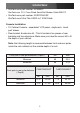
Instruction Manual s StarTech.com part number: SCNM9FF StarTech.com 10 ft. Cross Wired Serial/Null Modem Cable DB9 F/F s StarTech.com part number: SVECONUSXX StarTech.com Ultra-Thin USB 2-in-1 KVM Cable Console Installation s 1U Cabinet Console - assembled “LCD panel + keyboard + touch pad” drawer s Rear bracket & extension kit - This kit contains two pieces of rear brackets and two extensions. Make sure you have the correct kit to fit the depth of your cabinet.
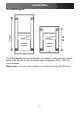
Instruction Manual Overhead Diagram KVM Module Console Drawer Console Drawer Depth Depth KVM Module The KVM Module can be connected to a console, or be used as a standalone KVM Switch. There are three major categories: PS/2, USB and Sun Interfaces. Please note: You can only connect to a computer using the PS/2 port.
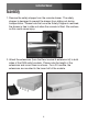
Instruction Manual Assembly 1. Remove the safety stopper from the console drawer. The safety stopper is designed to prevent the drawer from sliding out during transportation. Please note that once the Safety Stopper is removed, the drawer is free to slide out when the console is tilted. Be cautious, as this could cause injury. 2. Attach the extensions (from the Rear bracket & extension kit) to both sides of the KVM switch module. Please note the length of the extensions and mount them as shown.
Instruction Manual Please note the orientation of the wide side of the extension 3. Fasten the console to the rack, using the provided screws.
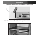
Instruction Manual 4. Slide the rear bracket into both sides of the unit, ensuring the three round screws are INSIDE the bracket track, while sliding inward (noting the arrows in the diagram below). 5.
Instruction Manual 6. Push the KVM switch module evenly toward the drawer: 7.
Instruction Manual 8. Make sure the C-36 connectors are firmly connected: 8mm (5/16”) C36 Connector 9. Connect the power supply to the power jack on the KVM module to complete the assembly.
Instruction Manual Hardware Guide Front Panel Functions 1 2 3 10 4 5 6 7 8 9 KVM Control and Status: (This section is effective only when a KVM switch module is connected.) 1. Computer Selection Pad - Press one of these pushbuttons to select a computer. For 16 port models, 1-8 represent the lower 8 ports, while A-H indicates the higher 8 ports. Port 1 and A share the same push button; if port 1 is already selected, tap its pushbutton to select port A.
Instruction Manual Keyboard Status and LCD Panel Power Switch: 7. Num Lock - Keyboard Num Lock status 8. Caps Lock - Keyboard Caps Lock status 9. Scroll Lock - Keyboard Scroll Lock status 10. LCD Panel Power Switch Rear Panel Functions 1 2 5 3 4 6 78 9 10 11 1. DC In 2. Link 3. Serial Port 4. VGA Out 5. R-Port 6. IP Setup button - Pressing this button (using a paperclip, etc.) will automatically load the On-Screen Display. 7.
Instruction Manual BYhkcf_ 7cbÏ[ifUh]cb CABCONS1716I offers four distinct methods for configuring the unit for your network. Which method will work best depends on your level of experience and your specific network configuration. Please note: Connecting the remote computers prior to following the steps outlined below can result in system instability. Please refrain from connecting the remote computers, until the local peripherals have been connected.
Instruction Manual If static IP addresses are assigned, you will likely need to change the Net Mask, IP Address and other details, prior to connecting via your Web browser. If this is the case, connect a local PS/2 keyboard and press the Enter key. In order to proceed, you will require an administrative username and password. By default, the username and password are admin. You will be given the opportunity to change the password (recommended) to be performed once the configuration is complete.
Instruction Manual log, since you will need to know the IP address of the unit to complete the configuration over your Web browser. (If you are unsure of how to access your network’s DHCP log, contact your System Administrator for details.) If the unit is powered on and connected to the network via the LAN port on the rear panel, it will automatically attempt to lease an IP address using DHCP.
Instruction Manual KYV 7cbÏ[ifUh]cb Ig]b[ GhUh]W =D Unlike the DHCP access method described above, some networks rely on static IP addresses wherein every device has a pre-configured IP address that does not change. To access the Web configuration for this product, you will need to configure the workstation you are using to the same subnet (255.255.255.0) and also assign it a valid IP address (i.e. 192.168.1.100).
Instruction Manual You can use the serial port on the CABCONS1716I to access the terminal configuration tool; to do so, you will require a null modem serial cable. Connect a female end of a serial cable to the serial port used for serial access on the host computer. Connect the opposite end to the CABCONS1716I. Configure the terminal software with “8N1” settings: Connection speed: 115200 bps No.
Instruction Manual Ig]b[ h\Y KYV =bhYfZUWY The Web interface is the most intuitive way to configure the CABCONS1716I. As it offers a Java-based VNC client that can be used to control the host computer from a remote location, as well as support for any industry-standard HTML Web browser. You can access the Web interface by opening your Web browser and entering the IP address of the CABCONS1716I you wish to configure.
Instruction Manual browser or the Java VNC client, always choose the option to continue.
Instruction Manual click on the Help button near the top right of each page to re-display it. Please note: The aforementioned sections of the Web Interface will remain on-screen, with selected categories displayed center screen. Main Menu selections Please note: Some of the following items may not be present, based on assigned user privileges (i.e. non-admin users will not see any items under the Admin category).
Instruction Manual tion options, VNC options, display and bandwidth options etc.), according to each user’s individual preferences. Please save your selections by clicking the Save Changes button. Snapshots: The Snapshots screen allows you to view and save a screenshot of the controlled computer in its current state. This screenshot will update periodically (automatically). Saved image files are stored in .PNG format. Logout: Clicking on Logout will terminate your Web Interface section.
Instruction Manual When disabled, the LAN port will use the values assigned to it on the IP Addresses and Routing table below. IP Addresses and Routing: This table allows you to assign IP information for the LAN and WAN ports separately. If you are using DHCP, the values for the LAN port will be filled in automatically and any changes made will not affect the setup. Domain Name Server: This section allows you to specify DNS servers and the default DNS domain suffix in use on the network.
Instruction Manual System Ident: Machine Name: This is the name that is used to uniquely identify this machine.You might want to create a DNS entry that matches this name. The name is provided as the Client Name for the DHCP server. It is also shown at the top of each page in the web browser interface and is the “desktop name” for VNC clients. Other identification details: These values are for information pur poses. They are visible from the VNC client and via SNMP (if enabled).
Instruction Manual power management device. SNMP: The SNMP menu allows you to configure the CABCONS1716I so it can be recognized and managed using industry standard Simple Network Management Protocol software. RADIUS: The RADIUS server requires the IP address, the UDP port number (1812 - default or 1645) and the shared secret. The shared secret is used to encrypt communications and corresponds to a shared password for the RADIUS server and the client machine.
Instruction Manual called GMT or Zulu) for all machines. If the computer you are using to view this page knows the correct time, just press the button to set the time and date to the same time as your browser. Firmware: The firmware on the Server Remote Control is field upgradeable. To upgrade to another version, login as admin. Auto Self Upgrade: The CABCONS1716I unit is able to upgrade itself over the Internet.
Instruction Manual NOTE: Remember the following during the firmware upgrade: s Do NOT turn off power to unit before this operation completes successfully. s The unit will sometimes reboot as part of the upgrade procedure, depending on which system component is upgraded.You will have to reconnect and re-login in those cases. s Wait at least two minutes after pressing Start. Do not assume the upload did not work, the upload could simply be slow.
Instruction Manual Copyright Menu: Provides the Terms of Use and other information related to the firmware and software on the CABCONS1716I. Using the Terminal Interface via Serial Port The terminal interface can be accessed via the serial port for configuration of the basic settings of the CABCONS1716I. While not intended to be a substitute for the Web interface, it does allow you to configure similar functions. The menu list below describes the options that can be modified through the terminal interface.
Instruction Manual modern browsers come with a version of Java that is compatible with this application. The Java VNC client makes a connection back to the Server Remote Control unit over port 5900 (by default) or 15900, if encrypted. The encrypted connection is a standard SSL (Secure Socket Layer) encrypted link that encrypts all data from the session, including the actual video pictures. Because Java is considered a “safe” programming language, the Java VNC client has some limitations.
Instruction Manual VNC require the flag -bgr233. For examples on using this flag, review the commands in the following section. SSH Tunnel (with Native VNC client) If you are using Openssh, the following Unix command is appropriate based on the default settings on a machine at 10.0.0.34: ssh -f -l admin -L 15900:127.0.0.1:5900 10.0.0.34 sleep 60 vncviewer -bgr233 127.0.0.1::15900 Same command, but using the WAN port: ssh -f -l admin -L 15900:127.0.0.1:5900 10.0.0.98 sleep 60 vncviewer -bgr233 127.0.0.
Instruction Manual Using the VNC Menu One of the unique features of this product is the VNC menu system. Whenever you see a window with a dark blue background and grey edges, this window has been inserted into the VNC data stream so that it is effectively laid over the existing video. These menus allow you to control the many features of the CABCONS1716I without using the web interface or a custom client.
Instruction Manual or PS/2 signals. If Autosync appears beneath this indicator, the mouse pointers on the local mouse and the VNC session will be synchronized automatically. Bandwidth: Indicates current average bandwidth coming out of the Server Remote Control unit. The second number measures round trip time (RTT) of the connection when it was first established. Resync: Re-aligns the remote and local mouse points so they are on top of each other.
Instruction Manual Main Menu To access the main menu, quickly press F7 twice.You must press the key twice within one second. If you press it once or too slowly, then the F7 key(s) are sent to the host, just like any other key. This is the only way to get into the menu system, if the Bribar is disabled. Here is the main menu for a typical system: The main menu window may be moved by clicking and dragging on the title bar.
Instruction Manual difference in speed and smoothness. s Mouse Resync: Resynchronizes the mouse pointer so that the local and remote mouse pointers are on top of each other. s PS/2 Reset: Resets the PS/2 emulation going to the host and to the attached PS/2 devices. This can be used if the mouse stops responding or the PS/2 keyboard isn’t working. s Take Control: When multiple users are connected to the same system, use this button to take control away from another user.
Instruction Manual VirtKeys Menu Clicking any button in the top half of the window simulates pressing and releasing the indicated key. In the bottom area of the screen, clicking will simulate the indicated Meta key being pressed.You may then click in the top part to send another key and release the Meta key at the same time. Alternatively, you may move the mouse outside this window, press the regular key, and then choose -RESET- to release all depressed keys.
Instruction Manual Video Tuning menu Use the Auto Everything button to automatically fine-tune all three adjustments. If the test pattern for Color Offset calibration is not present on the screen, then the Color Offset adjustment is skipped. Changes/frame indicates the number of 16x16 blocks of video that are being sent, on average, for every frame of video. With a static image being displayed by the server, this number will be zero (shown as -nil-).
Instruction Manual If the system cannot find the test pattern on the screen, check that the pattern isn’t scaled or covered up. (perform this operation in 24-bit or 32-bit color video mode (i.e. truecolor). Although the algorithm may work in 16-bit or 8-bit color video modes, the results will not be optimum and usually it won’t be able to recognize the test pattern. Pressing the Advanced button will open the Advanced Video Tuning menu.
Instruction Manual Accessing KVM Features Once you can access and configure the networking component of the Server Remote Control, you can use it to select and control the managed computers connected to it. This section describes how to add additional KVM switches to the master unit for greater flexibility, and how to use the on-screen display (OSD) system to manage your computers. Once you have established a VNC session, you can access the KVM features as though you were at a local console.
Instruction Manual OSD Operations By hitting the left key twice within two seconds, you may see the ‘Hotkey Menu’ if it is enabled (an OSD option). Or, by hitting the left key three times within two seconds, you will see a KVM MENU screen (below) showing a list of the computers with corresponding channel addresses, names and status. s The port number (or channel address) of the currently selected computer is displayed in red in the top right of the screen.
Instruction Manual OSD Function Keys You can use the function keys when the OSD menu is active. The Function key edits the name of a managed computer or a Slave KVM. First, use the and arrow keys to highlight a channel then press followed by name entry. Your name can be up to 14 characters long. Valid characters are A to Z, 0 to 9, and the dash character. Lowercase letters are converted to uppercase. Press to delete a letter one at a time.
Instruction Manual Auto Scan: In this mode, the KVM automatically switches from one powered computer to the next, sequentially in a fixed interval. During Auto Scan mode, the OSD displays the name of the selected computer. When Auto Scan detects any keyboard or mouse activity, it suspends the scanning until activity stops; it then resumes with the next computer in sequence. To abort Auto Scan mode, press the left twice. Scan Type and Scan Rate set the scan pattern.
Instruction Manual Keyboard Speed: The KVM offers a keyboard typematic setting that overrides the typematic settings in the BIOS and Windows operating system. Available speed options are Low, Middle, Fast and Faster as 10, 15, 20 and 30 characters/sec respectively. The Keyboard Speed setting is retained in non-volatile memory. Hotkey Menu: When you hit the left key twice within two seconds, the Hotkey Menu appears displaying a list of hot-key commands if the option is On.
Instruction Manual Hot Key Commands A hot key command is a short keyboard sequence to select a computer, activate a computer scan, etc. A hot-key sequence starts with two Left Control keystrokes followed by one or two more keystrokes. The short form hot-key menu can be turned on as an OSD function (: More\Hotkey Menu) every time the left key is pressed twice. Left refers to the key located at the left side of the keyboard.
Instruction Manual Manual Scan: Manual Scan enables you to manually switch back and forth between powered computers: left Ctrl + left Ctrl + F2. Press the up or down arrow to select the previous or next computer in sequence. Press any other key to abort the Manual Scan. NOTE: The Scan Type setting will determine whether computers must be eye-marked to be included in the scan.
Instruction Manual Changing Your Configuration After the initial power up, any device (either a KVM or a PC) can be added or removed from any PC x port on the KVM without having to power down the Master KVM Switch. Make sure that devices are turned off before connecting them to the Master KVM switch. Please note that after changing your configuration, the OSD will automatically update to reflect the new configuration.
Instruction Manual s Network latency, which is the total time it takes for a packet to get to the CABCONS1716I and come back, has the biggest impact on perceived performance and usability. s Network bandwidth has a lesser effect, particularly when just moving the mouse around. Only a few bytes need to be sent when the mouse is moving (and nothing else is changing on the screen), but the roundtrip-time limits the hand-eye coordination of the user if it is too great.
Instruction Manual is 10 units. s The ’-’ and ’+’ buttons decrease or increase the parameter by one unit. s The middle button sets the parameter to the middle value. The text of the middle button also indicates which parameter is being controlled. Note that in the case of phase, the middle button invokes the autophase algorithm. The Performance section of the screen gives an indication of the quality of the video.
Instruction Manual Ig]b[ h\Y AcXYa :YUhifY The Modem feature allows the CABCONS1716I to act as an Internet connection server for increased security and flexibility in connecting with the host computer. Unlike the TCP/IP connection used with the standard Web configuration and VNC clients, the modem creates a one-to-one connection between the CABCONS1716I and the computer you are using, bypassing the public Internet completely.
Instruction Manual CONS1716I. It is important to note that modems that offer “56K” (or 56,000 bps) connections often achieve connection speeds that are far lower than their maximum capabilities.
Instruction Manual The baud rate dictates the connection speed between the CABCONS1716I’s serial port and the modem, and does not affect the connection speed between the local and remote modems, as they will negotiate their own connection speed when a connection is made. It is highly recommended that this setting be left at the default for best performance.
Instruction Manual 7. Select Connect using a dial-up modem, then click Next. 8. In the space provided under ISP Name, type an appropriate name of your choosing for the connection. Click Next. 9. In the space provided under Phone Number enter the phone number for the line to which the CABCONS1716I’s modem is connected. You may need to add the area code, country code, or other digits needed to access the outside line as appropriate. When finished, click Next. 10.
Instruction Manual You can now login to the Web interface (and/or VNC session) normally. Note that the remote machine (the one you dialed from) is automatically assigned the IP address 99.99.99.100 for the PPP session. This, and the IP address of the CABCONS1716I, cannot be modified.
Instruction Manual Modem Troubleshooting Guide The following messages will appear in the system log on the Status screen in the Web interface and may help to diagnose problems with the modem configuration. Starting PPP (for auth) on port… Modem is connecting and the PPP login process is starting. Modem hang up. Resetting The connection has been closed or terminated unexpectedly. Timeout during login process.
Instruction Manual allows you to monitor and configure serial devices using the interactive Web interface. To minimize space and infrastructure requirements, the RPort modules use a single cable to carry both power and the data signal. All configuration settings are stored separately in each attached device in non-volatile memory so that they will not be lost in the event of a power outage or disconnection.
Instruction Manual table with the following headings: #:You can assign a value (1 ~ 99) to each attached serial remote control module. This does not affect the configuration or operation of the device in any way, but is simply a means to sort this list for ease of management. Name/Description: An identifier for the R-Port module. Like the number assignment, it is for ease of administration only.
Instruction Manual Advanced Configuration Using the Integrated SSH Shell In most cases, configuring the CABCONS1716I to the same settings as the R-Port devices you are connecting should allow the devices to work with a minimum amount of configuration. However, you can also change the default settings on each R-Port device to fit your preferences and the needs of your application. If you click the Connect… button next to the device you want to configure, two new windows will appear.
Instruction Manual the menu is active. These commands are not sent to the device you are managing and relate to the RPORT module itself. Remote Login via SSH You can also use a standard SSH client to access the R-Port options if you wish to avoid using the Java-based SSH client in the Web interface. Simply use your SSH client (several freeware packages are available for download, along with commercial applications) and connect to the IP address of the CABCONS1716I using port 22 (default).
Instruction Manual When reconnected, it will automatically become available after a 15 second initialization period. Any log entries will be retained by the R-Port module while deactivated, but will not be available to users until it is re-initialized.
Instruction Manual Installing the new certificate… The following instructions detail how to install the certificate from the CABCONS1716I onto your local computer (in this case, when using Internet Explorer with Windows XP): 1. Open your Web browser and go to the CABCONS1716I login screen. Click the Update security certificate link. 2. When prompted, choose Open. 3. A Window will appear that offers information about the certificate. Click Install Certificate. 4. The Certificate Import Wizard will appear.
Instruction Manual After resync, the mouse pointers are still not aligned Use the video adjust menu to position your video image exactly where required. Normally, a slight video positioning error is perceived as a mouse sync issue. A video positioning error is visible as a black line along the top or bottom (and right or left) edges of the remote screen.
Instruction Manual ?YmVcUfX FYd`UWYaYbh The keyboard is replaceable, in the event of language changes or maintenance. To replace the key-board, tilt it up, locate the mini-USB cable underneath the keyboard and unplug it gently. While installing the replacement keyboard, please ensure that you extend just enough of the cable to keep the keyboard flat inside the tray.
Instruction Manual the latch, then slide it outwards until the Touch Pad can be lifted up clear from the notches, as shown in the figure below (right side). The Touchpad is attached by a piece of mini-USB cable. To install the Touchad, extend just enough mini-USB cable and slide the Touch Pad all the way in till you hear a click sound as it is locked in position.
Instruction Manual GdYW]ÏWUh]cbg Console Connectors VGA (1), PS/2 Mouse (1), PS/2 Keyboard (1) Display Colors 16.
Instruction Manual HYW\b]WU` Giddcfh StarTech.com’s lifetime technical support is an integral part of our commitment to provide industry-leading solutions. If you ever need help with your product, visit www.startech.com/support and access our comprehensive selection of online tools, documentation, and downloads. Warranty Information This product is backed by a one-year warranty. In addition, StarTech.
StarTech.com has been making “hard-to-find easy” since 1985, providing high quality solutions to a diverse IT and A/V customer base that spans many channels, including government, education and industrial facilities to name just a few. We offer an unmatched selection of computer parts, cables, A/V products, KVM and Server Management solutions, serving a worldwide market through our locations in the United States, Canada, the United Kingdom and Taiwan. Visit www.startech.