
Instruction manual

3
Installation
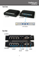
Hardware Installation
1. Place each VDSL Extender unit at their respective end-point
locations. Make sure an AC electrical outlet is located nearby.
2. Connect the included power adapters to the pair of VDSL Extender
units. The Power LED should light up solid.
3. Connect the “Line” RJ11 connector on the VDSL Extender units
either directly together with patch cabling, or to a buildings existing
analog telephone wiring. If the two units are able to successfully
communicate with each other, the “WAN” LED should light up solid.
OPTIONAL: If the telephone wiring is also used for POTS telephone
service, then a telephone may be connected to the “Phone” RJ11
connector on the VDSL Extender units.
4. Connect each computer, or Ethernet networking device to an
available RJ45 connector on the VDSL Extender units. The
respective LAN LED should light up to indicate a successful physical
connection.
Driver Installation
No driver or software installation is required.
Conguration
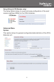
Web Interface
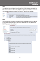
Each of the VDSL Extender units have a built-in web interface, for
configuring the router settings (WAN and LAN ports), if necessary.
The interface can be access via their IP addresses (CO Modem:
192.168.16.249, CPE Modem: 192.168.16.250). The default password
is: admin
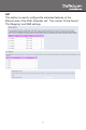
The main menu screen on the CPE Modem has two options: “Setup
Wizard” for quick setup, and “Advanced Setup” for a more customized
configuration. The CO Modem only has “Advanced Setup” options.