
User manual

35BAYPANELBK
Black 3.5” Drive Bay Multi-Port Panel
Package Contents
1 x 3.5” Front Panel•
1 x User Manual•
2 x Internal USB Cables•
1 x Internal IEEE 1394 Firewire and Audio Cable•
1 x IEEE 1394 External Cable•
1 x SATA Cable•
Installation
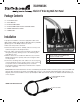
To prepare for installation, connect the appropriate cables to the
USB1, USB2, eSATA, 1394 (FireWire), MIC (Microphone) and SPK
(Speaker) ports on the Multiport Panel, as shown:
Make sure that your PC is turned off.1.
Remove the PC Case Cover. Similarly, remove a 3.5” bay cover 2.
from the front panel of the Computer Case.
Pass the cables (connected to the Bay Panel as shown above) 3.
through the open bay, allowing access to the remaining ends
from within the case.
With the cables now accessible from within the case, insert the 4.
Multiport Panel into the open bay and secure it using the small
screws provided.
Connect the remaining ends of the cables to the necessary ports 5.
on the motherboard. For the specific location of each connector
as it pertains to the host motherboard, please consult the
documentation that accompanied your motherboard or computer
at the time of purchase.
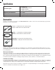
Please note: If the motherboard does not have an available (9-pin) FireWire header connection, please connect the IEEE 1394
external cable (included, shown below) to the IEEE 1394 connector on the internal 1394 FireWire/Audio cable (shown as 1 in
diagram), then insert the FireWire connector provided by the IEEE 1394 external cable into an available external FireWire port
on the computer.
1 3
2
1
15-pin Header - Internal IEEE 1394
Firewire and Audio Cable
2
eSATA - to SATA connection
3
2 x 9-pin USB header
To 35BAYPANELBK FireWire
internal cable
To external FireWire
port
IEEE 1394 External Cable