
Instruction manual

Instruction Manual
5
Remove a metal bracket that is adjacent to or near the one removed 5.
in step #2, and fasten PUSBADAP/PUSBADAPLP directly to the metal
rear panel of the computer case.
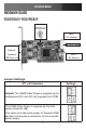
Connect the remaining end of the 9-Pin USB Header Cable used in 6.
step #3, to the USB IN connector, denoted as J1: USB Input
Connector (from Host USB port) (see diagram, pg.3) on the
PUSBADAP board.
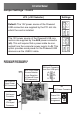
PCI312PUSB/PEX312PUSB:7. By default, JP2 (see pg. 3) is set to PCI.
The card will draw power via the PCI/PCI Express slot into which it is
installed; as such, if you’ve left the JP2 jumper in the default
position, there will be no need to connect PCI312PUSB to the
computer power supply.
If JP2 has been switched to INT (Internal), you must connect PCI
312PUSB/PEX312PUSB to the computer power supply, by inserting an
available LP4 connector into the AUX Power Connector.
PUSBADAP: By default, JP2 is set to INT, commanding the card to
draw power from the computer power supply. As such, insert an LP4
power connector from the power supply, into the AUX Power
Connector.
If JP2 has been set to EXT, the PUSBADAP will draw power through
the External Input Power DIN Connector, and will require an external
power source (see http://www.startech.com for accessories).
Once both cards have been properly positioned, and the necessary 8.
link has been made between them, close the computer case and
power on the computer.
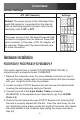
PCI312PUSB/LP or PEX312PUSB/LP Only
This section details how to install PCI312PUSB/PEX312PUSB as a stand
alone card.
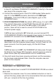
Remove the computer cover. For more detailed instruction on how to 1.
perform this step, please refer to the documentation that was included
with your computer at the time of purchase.