
Instruction manual

Instruction Manual
5
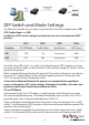
DIP Switch and Mode Settings
The Ethernet Extender Kit units have a 4-position DIP switch for conguration of CO/
CPE, Prole, Band, and SNR.
By default, all DIP switch settings for both units are set to the downward “OFF”
position.
For initial setup, DIP switch 1 is usually set to the downward (OFF) position, ensuring
the unit is set to CO mode, set the 2nd unit to CPE mode by setting DIP switch 1 to the
upward (ON) position.
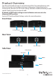
When using the Ethernet Extender Kit, one end (Transmitter or Receiver) must always
be set to “CO” (Central Oce), mode, while the opposite end must always be set to
“CPE” (Customer Premises Equipment) mode.
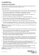
To ensure the Ethernet Extender Kit operates as intended with no problems,
errors, or disruptions, DIP switch settings 2 through 4 should be set to the same
position on both your Transmitter and Receiver Units.
CO or CPE Mode
Setting each unit to CO or CPE mode is usually based on which direction you want
the most bandwidth delivered. “Download” bandwidth, data sent from CO to CPE, is
generally higher than “Upload” bandwidth from CPE to CO.
If you need higher bandwidth from the Transmitter Unit to the Receiver Unit, set DIP
switch 1 to the downward (OFF) position at the transmitting end and the upward (ON)
position at the receiving end.
If you need higher bandwidth from the Receiver Unit to the Transmitter Unit, set DIP
switch 1 to the upward (ON) position at the receiving end, and the downward (OFF)
DIP1 DIP2 DIP3 DIP4
Function CO/CPE Mode Prole Mode Band Mode SNR Target
ON CPE 17a Symmetric 6dB
OFF CO 30a Asymmetric 9dB