SR200 Surface Roughness Tester User Manual
Table Of Contents Chapter 1 Using the SR200 with a PC 3.3 Introduction to Surface Texture Printing 3.3 terminology and definitions 1.1 To cancel print: 3.3 Surface Texture Definitions 1.1 Chapter 4 Menu Settings 4.1 Parameter Definitions 1.2 Main Menu 4.1 Ra 1.2 Cut off 4.1 Rp 1.2 Evaluation length 4.1 RSm 1.2 Parameters 4.1 Rz 1.2 Range: 4.3 Rz1max 1.2 Range Selector Table 4.3 Rt 1.2 Print Settings: 4.3 Rmr 1.3 Units: 4.3 RPc 1.3 Filter: 4.3 Rsk 1.
Specification for Data Dump 5.5 Chapter 6 Accessories 6.1 Chapter 7 Maintenance 7.1 Calibration 7.1 Reference Standard 7.1 Sensitivity Check and Adjustment 7.1 Cleaning the Stylus 7.1 Pick-up Skid 7.
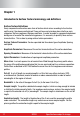
Chapter 1 Introduction to Surface Texture terminology and definitions Surface Texture Definitions Every components surface has some form of texture which varies according to its structure and the way it has been manufactured. These surfaces can be broken down into three main categories: Surface roughness, Waviness and Form. In order to predict a components behaviour during use or to control the manufacturing process, it is necessary to quantify these surface characteristics.
Note: almost all parameters are defined over one sample length, however in practice more than one sample length is assessed (usually five) and the mean calculated. This provides a better statistical estimate of the parameters measured value. Parameter Definitions Surface texture is quantified by parameters which relate to certain characteristics of the texture.
Rmr: Material Ratio is the length of bearing surface (expressed as a percentage of the evaluation length ln) at a depth below the highest peak. Replaces tp% - Bearing Ratio as defined in ISO 4287 - 1984 RPc: Peak Count The number of local peaks which project through a selectable band centred about the mean line or a line parallel to it.
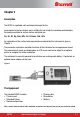
Chapter 2 Description The SR200 is a portable, self-contained instrument for the measurement of surface texture and is suitable for use in both the workshop and laboratory. Parameters available for surface texture evaluation are: Ra, Rz, Rt, Rp, Rmr, RPc, Rv, Rz1max, Rsk, Rda An explanation of the surface texture parameters evaluated by this instrument is given in Chapter 1. The parameter evaluations and other functions of the instrument are microprocessor based.
Traverse Unit The top panel of the traverse unit carries a membrane type control panel and a liquid crystal display. The unit houses the electronics for controlling the measurement sequence, computing the measurement data and outputting the results to the display, or to the RS232 port for use with a printer (when included) or to a computer, for further analysis. The unit also contains a drive motor which traverses the pickup across the surface to be measured.
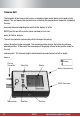
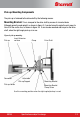
Pick-up Mounting Components The pick-up is fastened to the drive shaft by the following means: Mounting Bracket. This is clamped to the drive shaft by means of a knurled knob. Although normally used upright, as shown in figure 3, it can be turned to angle the pick-up or to take it off the centre line, as shown in figure 3a. It can also be mounted side-ways on the drive shaft, when the right angle pick-up is in use.
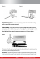
Figure 3a Figure 3b Adjustable Support: This can be clamped at any position on the slide of the mounting bracket to provide pick-up height adjustment. Pick-up holder: This fits into the crutch of the pick-up support and is held in place by a spring plunger. A biased holder, when used as shown in figure 3, exerts a biasing force on the pick-up (depending on which way the holder is inserted into the support crutch).
in the holder. It is advisable to connect the lead to the display-traverse unit first and then the pick-up. To connect the pick-up to the display-traverse unit: the pick-up has 2 threaded ends with location pins. Insert the location pin securely into the SR200 body and tighten the threaded collar. When the extension rod is used, the short pick-up lead is not required and the end of the rod itself is inserted into the holder.
Mounting: On a flat surface the display-traverse unit can be supported on its three feet. If a user wishes to make his own mounting bracket for the unit, the dimensions of the fixing holes are shown in figure 7. Figure 7 2.
Chapter 3 Getting Started Battery To insert a battery, open the compartment by sliding the door to the right and remove the door from the unit. Insert the battery, with the terminals positioned as shown in the diagram on the floor of the battery compartment.
Making a measurement Note 1: If the pickup has been changed or the instrument is being used for the first time, the instrument should be calibrated (see Chapter 7). Note 2: Successful use of the SR200 will only be possible if it is operated on a surface free from external vibration - see also operating notes in Chapter 5. Switching the SR200 ON Pressing the SCROLL key brings the display on and the previously selected set-up is displayed (provided power has been continuously present).
If multiple parameters have been selected they may not fit on the display. To continue viewing the remaining results, click on the SELECT key. To cancel a measurement If Measure is pressed during a traverse, a stop and reversal without measurement will occur and Measurement Cancelled is displayed.
Chapter 4 Menu Settings The operation of the SR200 is based on making selections from menus presented on the liquid crystal display. Two menu states exist, these are: Main Menu and Data Dump Menu. The Data Dump menu is accessed via the Main Menu and is used when connecting to a PC.
on the screen (see below). Press the SCROLL key left to right across the columns then press the SELECT key for each parameter required (multiple selections can be made). The SELECT key is also used to de-select a parameter. Ra RSm Rz Rz1max Rt Rsk Rmr > > > settings Rpc > > > settings Exit When selecting the Rmr and Rpc parameters, additional settings need to be specified. SCROLL onto “Settings” then click on the SELECT key.
Range: Allows the user to scroll through the range options. The most common settings are as follows: For surfaces <10 micron peak to valley- select range of 10µm For surfaces <100 micronpeak to valley- select range of 100µm For surfaces <300 micron peak to valley- select range of 300µm Range Selector Table Parameter Resolution Resolution Resolution at 10µm rangeat 100µm rangeat 300µm range Ra Rp Rz Rz1max Rt Rmr RPc Rsk Rda Rsm 0.01µm 0.01µm 0.01µm 0.01µm 0.01µm 0.1% 1 decimal point 0.001µm 0.
EVALUATION LENGTH RANGE UNITS FILTER DUMP MODE All other settings are carried out via the PC. SPC Mode If SPC is required, this can be switched on by pressing the PRINT and SCROLL key down simultaneously. The following warning screen will appear: Warning Changes to the following settings are for advanced functions only Quit OK Selecting OK displays the Select language and select SPC mode screen. Select the SPC Mode then SCROLL will toggle the mode between ON and OFF.
Selecting OK displays the Select language and select SPC mode screen. Select Language Select SPCmode Quit SCROLL down the options and SELECT Select Language English Français Deutsch Italiano OK SCROLL down the list of languages with and SELECT . This selection will remain as the default unless power is lost (eg battery is removed). 4.
Chapter 5 Making Measurements - Technical Considerations Operating Notes Before measurements are made, there are a few general points of procedure which should be observed. 1. The surface to be measured must be free from vibration and the instrument must be completely steady during a measurement. 2. Always turn the pick-up so that the stylus is visibly perpendicular to the surface to be measured. 3. Set the display-traverse unit so that the traverse is made parallel to the surface being measured. 4.
Cut off A few trial measurements made on different surfaces will soon demonstrate that on some, the results obtained are very dependent upon the cut-off selected. This shows that it is important to choose the cut-off to suit the surface. In general, fine surfaces require short cut-offs and rough surfaces a longer one. The table on the following page gives some guidance on suitable cut-offs.
Measure before print pressing PRINT key before measurement No parameter selected pressing PRINT key before selecting printout parameters pressing PRINT key when printer not connected or no computer Printer not connected connected to receive dump data. pressing PRINT key during data transmission to printer (stop Printing cancelled printing). Message displayed for 2 seconds.
Language of printout same as language of display The printout heading is shown below: Starrett SR200 Operator:… Date: …… Object: …… Cutoff = xxx mm Evaluation length = xxx mm Filter = xxx 5.
Specification for Data Dump The following format is used for data dump from SR200 to a PC. Transmission set up is as follows: Baud rate: Number of data bits Start bit: Stop bit: Parity: 9600 Baud 8 1 1 None Resolution Evaluation length selectable Range selectable Transmission Transmitted data is unfiltered Transmission data Data type Horizontal Vertical 0.5µm for Evaluation 10nm Length 8mm 1.0µm for Evaluation Length >8mm 0.25mm, 0.8mm, 1.25mm, 2.5mm, 4.00mm, 8.0mm, 12.5mm. 25.
Chapter 6 Accessories Replacement Standard pick-up (SR-112-1503) Details as the standard pick-up, (see figure 6 pg 2.5) 10mm (400min) stylus tip radius. Conforms to US specifications (ANSI B46.1). Small bore pick-up, 5µm (200µin) stylus tip radius (SR-112-1504) For general use in small bores, on narrow surfaces and in grooves, or with the skid supported independently of the surface being measured. On this pick-up the skid is integral with the stylus arm housing and is set further back from the stylus.
Recess pick-up, 5µm (200µin) stylus tip radius (SR-112-1506) This pick-up has an extended stylus and skid for measuring at the bottom of a recess, or between shoulders and flanges up to 5.7mm deep. A special deep recess pick-up is available for measuring up to a depth of 25mm. Figure 12: The recess pickup Extension rod (SR-112/1510) 200mm long extension with integral lead, fits between the pick-up and carriage. The extension rod is fitted to the pick-up in the following manner: 1.
Chapter 7 Maintenance Calibration Reference Standard The sensitivity of the instrument is checked with the reference specimen supplied. This comprises a ruled surface having an Ra value accurate to within 4% of the value marked on its mount. To provide confidence in results, it is recommended that a sensitivity check is made at the beginning of each shift. Sensitivity Check and Adjustment The procedure for checking and adjusting the pick-up sensitivity is as follows: 1.