Hardware Manual
Federal Communications Commission Radio Frequency Interference Statement This equipment has been tested and found to comply with the limits for a Class A digital device, pursuant to Part 15 of the FCC Rules. These limits are designed to provide reasonable protection against harmful interference when the equipment is operated in a commercial environment.
TABLE OF CONTENTS 1. Unpacking and Installation ................................................................................................................... 1 1-1. Unpacking ................................................................................................................................... 1 2. Parts Identification and Nomenclature ................................................................................................ 3 2-1. U Model ............................................
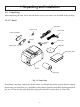
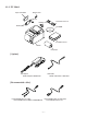
1. Unpacking and Installation 1-1. Unpacking After unpacking the unit, check that all the necessary accessories are included in the package. 1-1-1. U Model USB cable Switch cover Power cord Paper roll holder Screws Ferrite core Rubber feet Holder plate CD-ROM Installation sheet Printer Roll paper Fig. 1-1 Unpacking If anything is missing, contact the dealer where you bought the printer and ask them to supply the missing part.
1-1-2. PU Model Paper roll holder Switch cover Screws Rubber feet Holder plate Connector cover A CD-ROM Installation sheet Printer Roll paper [Options] AC adapter STAR, Adapter PS60A-24A USB cable STAR, USB Cable 1.
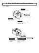
2. Parts Identification and Nomenclature 2-1. U Model Printer cover Open this cover to load or replace paper. Cover open lever Pull this lever in the direction of the arrow to open the printer cover. Power switch Used to turn on/off power to the printer. Control panel Features LED indicators to indicate printer status and switches to operate the printer. USB connector Peripheral drive connector For connection to a host computer using a USB cable. Connects to peripheral units such as cash drawers, etc.
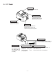
2-2. PU Model Printer cover Open this cover to load or replace paper. Cover open lever Pull this lever in the direction of the arrow to open the printer cover. Power switch Used to turn on/off power to the printer. Control panel Features LED indicators to indicate printer status and switches to operate the printer. Power connector For connection of the AC adapter or the PoweredUSB cable (Y cable). USB connector For connection to a host computer using the USB cable or PoweredUSB cable (Y cable).
2-3. Choosing a place for the printer Before actually unpacking the printer, you should take a few minutes to think about where you plan to use it. Remember the following points when doing this. ✓ Choose a firm, level surface where the printer will not be exposed to vibration. ✓ The power outlet you plan to connect to for power should be nearby and unobstructed. ✓ Make sure that the printer is close enough to your host computer for you to connect the two.
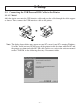
3. Setup 3-1. Connecting the USB/PoweredUSB Cable to the Printer 3-1-1. U Model Affix the ferrite core onto the USB interface cable and pass the cable through the cable support as shown. Then, connect the USB interface cable to the printer. Note: The dialog shown below may appear on your PC screen if your PC is running Windows 98 or Me, and if you turn ON the power of the printer for the first time while the PC and the printer are connected with the USB cable.
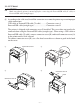
3-1-2. PU Model CAUTION Make sure that the printer is turned off before connecting the PoweredUSB cable (Y cable) or PoweredUSB cable (straight type). (1) According to the cable used, install the connector cover onto the printer to prevent improper cable connections. USB cable or PoweredUSB cable (Y cable) .......... Connector cover A PoweredUSB cable (straight type) ......................... Connector cover B The printer is shipped with connector cover B installed.
Note: The dialog shown below may appear on your PC screen if your PC is running Windows 98 or Me, and if you turn ON the power of the printer for the first time while the PC and the printer are connected with the USB/PoweredUSB cable. In this case, refer to the software manual on the CD-ROM, in the following directory: Documents folder. (2) Connect the interface cable to the printer as shown. When using the USB cable, secure the cable with the hook.
3-2. Connecting to a Peripheral Unit You can connect a peripheral unit to the printer using a modular plug. The following describes how to install the ferrite core and make the actual connection. See “Modular plug” on page 30 PoweredUSB for details about the type of modular plug that is required. Note that this printer does not come with a modular plug or wire, so it is up to you to obtain one that suits your needs.
3-3. Loading the Roll Paper Be sure to use roll paper that matches the printer’s specification. When using a paper roll with an 57.5 mm width, install the paper roll holder as described on the following page. Cover open lever Roll paper 1) Push the cover open lever, and open the printer cover. 2) While observing the direction of the roll, set the paper roll into the hollow, and pull on the leading edge of the paper toward you.
Note: When using a paper roll with an 57.5 mm width, install the paper roll holder in the groove in the printer. If a paper roll with a 57.5 mm width has been used, a paper roll with a 79.5 mm width cannot be used. (Changing from the smaller roll to a larger roll will cause part of the print head to rub against the platen and deteriorate.) Paper roll holder 3) Push down both sides of the printer cover to close. Note: Make sure that the printer cover is securely closed.
WARNING • Do not touch the cutter blade. - There is a cutter inside the paper outlet slot. Not only should you not put your hand in the paper outlet slot while printing is in progress, never put your hand into the outlet even when printing is not in progress. - The printer cover can be opened when replacing the paper. However, since the cutter blade is on the inside of the printer cover, be careful not to place your face or hands too close to the cutter blade.
3-4. Connecting the USB/PoweredUSB Cable to the PC 3-4-1. U Model Connect the USB interface cable to a USB port of your PC. Note: The dialog shown below may appear on your PC screen if your PC is running Windows 98 or Me, and if you turn ON the power of the printer for the first time while the PC and the printer are connected with the USB cable. In this case, refer to the software manual on the CD-ROM, in the following directory: Documents folder. 3-4-2.
Note: The dialog shown below may appear on your PC screen if your PC is running Windows 98 or Me, and if you turn ON the power of the printer for the first time while the PC and the printer are connected with the USB/PoweredUSB cable. In this case, refer to the software manual on the CDROM, in the following directory: Documents folder. 3-5. Installing the Printer Software Here is the procedure for installing the printer driver and utility software, which are stored on the supplied CD-ROM.
3-6. Connecting the Power Cord 3-6-1. U Model Note: Before connecting/disconnecting the power cord, make sure that power to the printer and all the devices connected to the printer is turned off. Also make sure the power cable plug is disconnected from the AC outlet. (1) Check the label on the back or bottom of the printer to make sure its voltage matches that of the AC outlet. Also make sure the plug on the power cord matches the AC outlet.
3-6-2. PU Model Note: Before connecting/disconnecting the AC adapter, make sure that power to the printer and all the devices connected to the printer are turned off. Also make sure the power cable plug is disconnected from the AC outlet. (1) Connect the AC adapter to the power cable. Note: Use only the standard AC adapter and power cable. (2) Connect AC adapter to the connector on the printer. (3) Insert the power cable plug into an AC outlet.
3-7. Turning Power On Make sure that the Power cord has been connected as described in 3-6. (1) Turn ON the power switch located on the front of the printer. The POWER lamp on the control panel will light up. Power switch CAUTION We recommend that you unplug the printer from the power outlet whenever you do not plan to use it for long periods. Because of this, you should locate the printer so that the power outlet it is plugged into is nearby and easy to access.
4. Attaching the Accessories The following accessories do not necessarily have to be attached. Attach them if necessary. • Holding plate • Rubber feet • Switch cover 4-1. Attaching the Holder Plate (1) Attach the holding plate to the printer. Then tighten the two screws that were supplied to secure it in place. (2) Position the printer over the screws, etc., on the wall and then slide it downward to set it in place. (3) Push the cover open lever, and open the printer cover.
4-2. Attaching the Rubber Feet (1) Attach the four rubber feet in the positions shown in the figure. Ensure that any soiling has been completely wiped off before attaching the rubber feet. (2) Push the cover open lever, and open the printer cover. (3) Insert the roll paper as shown.
4-3. Switch Cover Installation It is not necessary to install the switch cover. Only install it if it is necessary for you. By installing the switch cover, the following become possible. • Preventing the power switch from being operated by mistake. • Ensuring that other people can not easily operate the power switch. Install the switch cover as shown in the diagram below. The power switch can be turned ON (!) and OFF (O) by inserting a narrow instrument (ball pen etc.) in the holes in the switch cover.
5. Thermal Roll Paper Specification When consumable parts have run out, use those specified below. 5-1. Roll paper specification Thermal paper Thickness: 65~85 µm (excluding Mitsubishi HiTec F5041) Width: 79.5±0.5 mm (57.5±0.
5-2-2.
6. Control Panel and Other Functions 6-1. Control Panel 1 POWER lamp (Green LED) Lights when the power is ON. 2 ERROR lamp (Red LED) Indicates various errors in combination with POWER lamp. 3 FEED button Press the FEED button to feed roll paper. 3 FEED button 2 ERROR lamp (Red LED) 1 POWER lamp (Green LED) 6-2. Errors 1) Automatically recoverable errors Error Description Head high temperature detection Board high temperature detection Cover open error POWER Lamp Flashes at 0.
2) Non-recoverable errors Error Description Head thermistor error Board thermistor error VM voltage error VCC voltage error EEPROM error USB error CPU error RAM error POWER Lamp Flashes at 0.5-second intervals Flashes at 2-second intervals Off Flashes at 1-second intervals Flashes at 0.25-second intervals Flashes at 5-second intervals Off Off ERROR Lamp Flashes at 0.5-second intervals Flashes at 2-second intervals Flashes at 1-second intervals Flashes at 1-second intervals Flashes at 0.
6-3. Self-Printing Test Printing Turn the power ON while holding the FEED button depressed. Test printing is performed. The version number and printer settings are printed. After the printer starts printing, release your hand from the FEED button. After self-printing is completed, the printer will start in the normal mode.
7. Preventing and Clearing Paper Jams 7-1. Preventing Paper Jams The paper should not be touched during ejection and before it is cut. Pressing or pulling the paper during ejection may cause a paper jam, paper cutting failure or line feed failure. 7-2. Removing Paper Jam If a paper jam occurs, clear it as described below. (1) Set the power switch to off to turn off power to the printer. (2) Push the cover open lever, and open the printer cover.
7-3. Releasing a Locked Cutter (Auto Cutter Mode only) If the auto cutter locks up or fails to cut the paper, follow the steps below. WARNING Since working on the cutter may be dangerous, be sure to turn off the printer first. (1) Set the power switch to OFF to turn off the printer. (2) Remove the front cover to reveal the auto cutter. (3) Remove any jammed paper. Note: Be careful not to damage the printer while removing any jammed paper.
(4) If the cutter is locked, insert a Philips screwdriver into the Philips screw hole on the side of the cutter, and turn it in the direction of the arrow shown on the right, in order to return the cutter to its normal position. (5) Open the printer cover, remove any jammed paper, and then reinstall the paper roll. (6) Install the front cover, and then set the power switch to ON.
8. Periodical Cleaning Printed characters may become partially unclear due to accumulated paper dust and dirt. To prevent such a problem, paper dust collected in the paper holder and paper transport section and on the surface of the thermal head must be removed periodically. Such cleaning is recommended to be carried out once six month or one million lines. 8-1. Cleaning the Thermal Head To remove blackish dust collected on the surface of the thermal head, wipe it with Isopropyl alcohol (IPA).
9. Peripheral Unit Drive Circuit Peripheral unit drive circuit connector only connects to peripheral units such as cash drawers, etc. Do not connect it to a telephone. Use cables which meet the following specifications.
Notes: 1. Pin 1 must be shield drain wire connected to peripheral device frame ground. 2. It is not possible to drive two drives simultaneously. 3. The peripheral drive duty must satisfy the following: ON time / (ON time + OFF time) 0.2 4. Minimum resistance for coils L1 and L2 is 24Ω. 5. Absolute maximum ratings for diodes D1 and D2 (Ta = 25°C) are: Average Rectified Current Io = 1A 6.
10. Specifications 10-1. General Specifications Printing method Print speed Dot density Printing width Roll paper (6) Overall dimension (7) Weight (8) Noise Approx. Direct line thermal printing Max. 1000 dots/sec. (125 mm/sec.) 203 dpi: 8 dots/mm (0.125 mm/dot) Max. 72 mm Refer to chapter 5 for details on the recommended roll paper. Paper width:79.5±0.5 mm (57.5±0.5 mm when the paper roll holder is used) Roll diameter: ø83 mm or less 142 (W) × 204 (D) × 132 (H) mm Auto cutter model : 1.
10-2. Auto Cutter Specifications (1) Cutting frequency (2) Thickness of paper Max. 20 cuts per minute 65~85 µm 10-3. Interface (1) Specifications (2) Connector U Model PU Moedl USB 2.0 full speed Printer class and vendor class compatible Type B Type B and PoweredUSB connector Type B connector: DUSB-BRA42-T11(D2)-FA (manufacturer: DDK) Pin No.
10-4-2. PU Model (AC adapter) (1) Input: 100 to 240V AC, 50/60 Hz (2) Output: DC 24V ± 5% (3) Current Consumption (DC 24 V at room temperature) Low-power consumption mode: Stand-by: Approx. 0.1A Mean: Approx. 1.0A (at ASCII continuous printing) Peak: Approx. 5.0A (at print duty 100%, for 10 seconds or less) Standard mode: Stand-by: Approx. 0.1A Mean: Approx. 1.4A (at ASCII continuous printing) Peak: Approx. 10.
10-4-3. PU Model (PoweredUSB cable) When using the PoweredUSB cable, DC 24 V must be supplied to the printer from the system. Use a power supply for the printer that meets the following requirements. Power Requirements (1) Output: DC 24V ± 5% (2) Current Consumption (DC 24 V at room temperature) Low-power consumption mode: Stand-by: Approx. 0.1A Mean: Approx. 1.0A (at ASCII continuous printing) Peak: Approx. 5.0A (at print duty 100%, for 10 seconds or less) Standard mode: Stand-by: Approx. 0.
10-5.
10-6. Reliability 1) Life Mechanical: Head: Auto cutter: 20 million lines 100 million pulses, 100 km (±15% max. average head resistance fluctuation) For 2-color printing, 50 million pulses, 50 km (±15% max. average head resistance fluctuation) 1 million cuttings (provided the paper thickness is between 65 and 85 µm) Average printing ratio: 12.
11. DIP Switch Settings There are DIP switches located on the bottom of the PU model printers and various settings can be performed as shown in the following table. When changing the settings, use the following procedure. Note: For U model printers, the DIP switch settings do not need to be performed. (1) Turn the printer off and disconnect the power cable plug from the AC outlet. (2) Remove the screw, and then remove the DIP switch cover on the bottom of the printer.
ELECTRONIC PRODUCTS DIVISION STAR MICRONICS CO., LTD. OVERSEAS SUBSIDIARY COMPANIES STAR MICRONICS AMERICA, INC. 536 Nanatsushinya, Shimizu-ku, Shizuoka, 424-0066 Japan Tel: 0543-47-0112, Fax: 0543-48-5013 1150 King Georges Post Road, Edison, NJ 08837-3729 U.S.A. Tel: 732-623-5555, Fax: 732-623-5590 Please access the following URL http://www.star-m.jp/eng/dl/dl02.htm for the latest revision of the manual. STAR MICRONICS U.K. LTD.