RS 232C SERIAL TO PARALLEL CONVERTER RS 232C SERIELL-PARALLEL-KONVERTER RS 232C CONVERTISSEUR SÉRIE PARALLÈLE RS 232C CONVERTITORE SERIALEPARALLELO SPC-8K USERS MANUAL BEDIENUNGSHANDBUCH GUIDE D’UTILISATION MANUALE OPERATIVO 80821621
Federal Communications Commission Radio Frequency Interference Statement This equipment has been tested and found to comply with the limits for a Class B digital device, pursuant to Part 15 of FCC Rules. These limits are designed to provide reasonable protection against harmful interference in a residential installation.
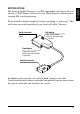
Please read this manual completely before proceeding to “power-up”! This will ensure successful operation of your Serial to Parallel Converter. Serial Connector DIP Switch Connect to the Serial Cable. Sets serial mode. Refer to the following section. Clear Button Clears the internal buffer when this button is pressed. Parallel Connector Connect to the printer. In addition to the converter, you will also need a proper serial cable.
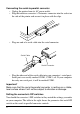
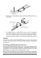
Connecting the serial-to-parallel converter • Unplug the printer from its AC power outlet. • Plug the interface converter’s Centronics connector into the socket on the side of the printer and secure it in place with the clips. • Plug one end of a serial cable into the serial connector. Serial Cable Serial Connector • Plug the other end of the serial cable into your computer’s serial ports. Serial ports are usually marked COM1, COM 2, etc.
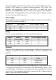
The tables below show all of the settings you can make with the serial-toparallel’s DIP switches to control certain parameters. The tables also include the matching settings you have to make in your MS-DOS AUTOEXEC.BAT file or with the Ports option of the Windows Control Panel. The highlighted cells in the tables indicate default settings for the serial-to-parallel converter. Data Length Data length is the number of bits that the computer transmits as one unit (byte) of data. This setting is normally 8.
Some programmers call the XON and XOFF control codes “kiss on and kiss off”; others call the same protocol DC1 and DC3 (for device control). Either way, these codes are used to let your printer control the flow of data, telling the computer when to start and stop sending data. Your printer asks to have data held back when its memory is nearly full or when it senses an ERROR condition. DTR (Data Terminal Ready) protocol does the same thing slightly differently.
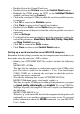
• Double-click on the Control Panel icon. • Double-click on the Printers icon in the Control Panel window. • Highlight the STAR printer on LPT1 in the Installed Printers window, and then click on Connect. • Click on the serial port (COMn) to which the serial-to-parallel converter is connected. • Click OK to return to the Printers window. • Click Close to return to the Control Panel window. • Double-click on Ports, and the Ports dialog box appears.
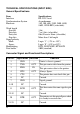
TECHNICAL SPECIFICATIONS (INPUT SIDE) General Specifications Item Interface Synchronization System Baud rate Specifications RS-232C-level Asynchronous 150, 300, 600, 1200, 2400, 4800, 9600, 19200 BPS (selectable) Word length Start bit: Data bits: Parity bit: Stop bits: Signal polarity Mark: Space: Handshaking Data buffer 1 bit 7 or 8 bits (selectable) Odd, Even or None (selectable) More than 1 bit length Logic “1” (–3V to –15V) Logic “0” (+3V to +15V) DTR, XON/XOFF, ETX/ACK 8KB (standard) Connector Sign
Bitte lesen Sie dieses Handbuch vollständig durch, bevor Sie die Initialisierung durchführen. Dies gewährleistet erfolgreiche Arbeit mit Ihrem Seriellen Interface-Konverter. Serieller Anschluß DIP-Schalter Mit dem seriellen Kabel verbinden. Zum Einstellen der seriellen Betriebsbedingungen. Siehe dazu den folgenden Abschnitt. Löschtaste Löscht den internen Puffer, wenn diese Taste gedrückt wird. Parallel-Anschluß Zum Anschließen des Druckers.
• Ein Ende des seriellen Kabels in den seriellen Anschluß des Konverters einstecken. Serielles Kabel Serieller Anschluß • Das andere Ende des seriellen Kabels in den seriellen Ausgang/Anschluß Ihres Computers einstecken. Serielle Ausgänge sind üblicherweise durch COM1, COM2 etc. gekennzeichnet. Wenn Ihr Computer nur einen seriellen Ausgang hat, so ist dieser mit COM1 gekennzeichnet.
Parameter vornehmen können. Die Tabellen enthalten auch die erforderlichen Einstellungen, die Sie in Ihrer MS-DOS AUTOEXEC.BAT-Datei oder bei den Anschlußoptionen der Windows-Systemsteuerung vornehmen müssen. Die markierten Kästchen in der Tabelle geben die Standardeinstellungen des Seriellen Interface-Konverters an. Datenlänge Die Datenlänge ist die Zahl der Bits, die der Computer als Dateneinheit (Byte) überträgt. Die Einstellung ist normalerweise 8.
Einige der Programme nennen die Steuerbefehle XON und XOFF “kiss on und kiss off” (mit Kuß einleiten und mit Kuß abschließen”); andere nennen das gleiche Protokoll DC1 und DC3 (zur Gerätesteuerung). Wie auch immer, diese Steuerbefehle ermöglichen Ihrem Drucker, den Datenfluß zu steuern, dem Computer mitzuteilen, wann er mit dem Senden von Daten beginnen und wann er damit aufhören soll.
• Öffnen Sie im Windows Programm-Manager die Hauptgruppe durch Klicken auf das dazugehörige Symbol. • Doppelklick auf das Symbol Systemsteuerung. • Doppelklick auf das Symbol Drucker im Fenster Systemsteuerungen. • Den STAR-Drucker unter LPT1 im Fenster Installierte Drucker markieren und auf Anschließen klicken. • Klick auf den seriellen Ausgang/Anschluß (COMn), an den der SeriellParallel-Konverter angeschlossen ist. • Klick auf das Schaltfeld OK, um in das Fenster Drucker zurückzukehren.
TECHNISCHE DATEN (EINGABESEITE) Allgemeine Technische Daten Bezeichnung Schnittstelle Synchronisationssystem Baudrate Wortlänge Startbit: Datenbit: Paritätsbit: Daten RS-232C-Format Asynchron 150, 300, 600, 1200, 2400, 4800, 9600,19200 BPS (einstellbar) 1 Bit 7 oder 8 Bits (einstellbar) Ungerade, gerade oder keine (einstellbar) Länge mehr als 1 Bit Stoppbits: Signalpolarität Kennzeichen (Mark): Logisch “1” (-3 V bis -15 V) Abstand (Space): Logisch “0” (+3 V bis +15 V) Protokoll: DTR, XON/XOFF, ETX/ACK Dat
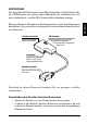
INTRODUCTION Le convertisseur série/parallèle est une unité série compatible EIA permettant d’interfacer les imprimantes STAR avec pratiquement tout microprocesseur nécessitant une interface EIA (série) standard. Connecteur série Interrupteur DIP Se connecte au câble série. Définit le mode série. Veuillez vous reporter à la section suivante.
Connexion du convertisseur série/parallèle • Débranchez l’imprimante de la prise secteur. • Branchez le connecteur Centronics du convertisseur d’interface sur la fiche située sur le côté de l’imprimante et fixez-la en position au moyen des pinces prévues à cet effet. • Branchez une extrémité du câble série au connecteur série. Câble série Connecteur série • Branchez l’autre extrémité du câble série à un des ports série de l’ordinateur. Les ports série sont généralement annotés COM1, COM2, etc.
Les tableaux ci-dessous illustrent tous les réglages que vous pouvez effectuer au moyen des interrupteurs DIP du convertisseur série/parallèle pour contrôler certains paramètres. Ces tableaux indiquent également les valeurs correspondantes que vous devez sélectionner dans votre fichier AUTOEXEC.BAT sous MS-DOS ou au moyen de l’option Ports dans le Panneau de configuration de Windows. Les cellules mise en évidence dans les tableaux indiquent les valeurs par défaut du convertisseur série/parallèle.
«handshaking» ou «prise de contact») signifie en fait «qui dit quoi et quand». Il permet à l’imprimante d’indiquer à l’ordinateur qu’elle est prête à recevoir des données. L’ordinateur et l’imprimante communiquent entre eux en envoyant des codes de protocole (qui sont situés au début de la table ASCII). Certains programmeurs appellent les codes de commande XON et XOFF codes CI1 et DC3 (acronymes de device control ou contrôle de périphérique).
Configuration d’une connexion série sur ordinateur exécutant Windows N’oubliez pas que les valeurs configurées sur l’ordinateur doivent correspondre à celles définies au moyen des interrupteurs DIP du convertisseur. • Dans le Panneau de configuration de Windows, sélectionnez le Groupe principal en cliquant sur l’icône associée. • Cliquez deux fois sur l’icône du Panneau de configuration. • Cliquez deux fois sur l’icône Imprimantes dans la fenêtre Panneau de configuration.
CARACTERISTIQUES TECHNIQUES (COTE IMPRIMANTE) Caractéristiques générales Elément Interface Système de synchronisation Vitesse en bauds Caractéristiques Niveau RS-232C Asynchrone 150, 300, 600, 1200, 2400, 4800, 9600, 19200 bit/seconde (pouvant être sélectionnée) Longueur de mot Bit de départ : Bits de données : Bit de parité : 1 bit 7 ou 8 (pouvant être sélectionnés) Impair (odd), pair (even) ou aucun (none) (pouvant être sélectionné) Plus d’1 bit de longueur Bits d’arrêt : Polarité de signal Forcée à 1
INTRODUZIONE Questo convertitore seriale-parallelo è un dispositivo seriale compatibile EIA (Electronic Industries Association) in grado di interfacciare le stampanti STAR con quasi tutti i microprocessori che richiedono un interfacciamento EIA (seriale) standard. Connettore seriale Interruttori DIP Collegare al cavo seriale. Impostazione dei parametri di comunicazione seriale. Leggere la seguente sezione.
Collegamento del convertitore d’interfaccia seriale-parallelo • Scollegate la stampante dalla presa elettrica. • Collegate il connettore Centronics del convertitore d’interfaccia alla presa posta sul lato della stampante e bloccatelo con gli appositi fermagli. • Collegate un’estremità del cavo seriale al connettore seriale. Cavo seriale Connettore seriale • Collegate l’altra estremità del cavo seriale ad una porta seriale del vostro computer.
Le tabelle sotto illustrano tutte le combinazioni di interruttori DIP che è possibile eseguire per configurare determinati parametri. In tali tabelle sono indicati anche i corrispondenti valori che dovrà contenere il file MS-DOS AUTOEXEC.BAT o che bisognerà specificare nell’opzione Porte del Pannello di Controllo di Windows. Le caselle della tabella evidenziate indicano le impostazioni predefinite del convertitore seriale-parallelo.
con cui la stampante comunica al computer che è pronta a ricevere dati. Il computer e la stampante comunicano tra loro inviandosi caratteri di controllo relativi al protocollo (situati all’inizio della tabella ASCII). Alcuni programmatori chiamano i codici di controllo XON e XOFF “kiss on e kiss off”; altri chiamano lo stesso protocollo DC1 e DC3 (per il controllo del dispositivo).
Configurazione di una porta seriale in ambiente Windows Ricordate che le impostazioni che eseguirete sul computer dovranno corrispondere a quelle degli interruttori DIP. • Dal Program Manager di Windows, aprite il gruppo Principale facendo clic sulla sua icona. • Fate doppio clic sull’icona del Pannello di Controllo. • Fate doppio clic sull’icona Stampanti nella finestra del Pannello di controllo.
SPECIFICHE TECNICHE (LATO DI INPUT) Specifiche generali Caratteristica Interfaccia Sistema di sincronizzazione Velocità di trasmissione Specifiche RS-232C Asincrono 150, 300, 600, 2400, 4800, 9600, 19200 BPS [selezionabile dall’utente] Lunghezza parola Bit d’inizio: Bit di dati: Bit di parità: 1 bit 7 o 8 bit (selezionabile dall’utente) Dispari, Pari o Nessuno (selezionabile dall’utente) Maggiore di 1 bit Bit di stop: Polarità del segnale Mark: Space: Handshaking Buffer di dati Stato logico “1” (da -3V
Customer response Worldwide Headquarters STAR MICRONICS CO., LTD. 536 Nanatsushinya, Shimizu, Shizuoka, 424, Japan North and South America Markets STAR MICRONICS AMERICA, INC. 70- D Ethel Road West Piscataway, NJ 08854 European Market STAR MICRONICS DEUTSCHLAND GMBH Westerbachstraße 59 D-60489 Frankfurt F.R. of Germany U.K. Market STAR MICRONICS U.K. LTD. Star House Peregrine Business Park Gomm Road, High Wycombe Bucks. HP13 7DL, U.K. Australian Market STAR MICRONICS PTY. LTD.