
Installation Guide
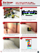

Required Tools.
100 FIELD LAYOUT OF WALL
PANELS, INSTALLATION GUIDE
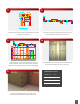
Determine greatest projection (bump out in wall). This will
determine the face of the panels. Discuss the layout options
with the GC. If there is a large bump you have two options,
shim out most of your furring or have the projection corrected.
Look around the project’s site conditions and plans, you
need to know what you are laying out and identify any
changes from the plan.
If the project is simple, shimming out the furring works well. If the panels
have other constraints, you need to be very careful. There are many
possible conflicts when furring out large areas, panel alignments, widths of
door jambs, electrical build outs, held dimension, are just a few examples.
Find high point of floor, check to see if the project has
a pre-set horizontal bench mark. If not set your own
horizontal bench mark.
Review the section details for all the panel intersections (many can be
downloaded from starhanger.com). On large projects it works well
to print out full scale inside corners, outside corners, door jambs and
any other complex areas. Then simply spray adhesive the layout in
3 4
5 6
1 2
970
E
970
E
SCALE:
ARCH. REF:
A
970
JAMB ELEVATION (RUN LEVEL @ 1 1/2" OUT FLOOR)
1/2" = 1'-0"
PER JOB
970
E
970
E
970
E
970
E
6
3
4
"
76"
100"
CEILING HEIGHT = 8'-6" (106")
1
2
"
6"
CEILING HEIGHT = 107
1
2
" (@ HIGHEST POINT)
7
1
2
" (MAX.)
26
1
2
" (MAX.)
98" (MAX.)
96
1
2
" (MIN.)
25" (MIN.)
6" (MIN.)
3. SCRIBE ALL BASEBOARD TO THE FLOOR
FROM THE MASTER REFERENCE POINT.
FROM THE MASTER REFERENCE POINT.
2. SCRIBE ALL DOOR JAMBS AND CASED OPENINGS TO THE FLOOR
1. ALL DIMENSIONS TO BE REFERENCED FROM THE FINISHED CEILING
NOTES
FLOOR CONDITIONS. THIS IS TYPICAL WHERE ALIGNMENT OF ITEMS IS NECESSARY.
THIS ELEVATION SHOWS LEVELING HEADERS FROM A MASTER REFERENCE POINT AT VARYING
FINISHED FLOOR @ LOWEST POINT
FINISHED CEILING
FINISHED FLOOR @ HIGHEST POINT
DASHED LINE DENOTES LEVEL FLOOR LINE
CONTROL LINE
STORY PLOE
TOP OF JAMB
MASTER
REFERENCE
POINT
%%UJAMB INSTALLATION
1.) CONTROL LINE FOR ELEVATION.
GWBD
DETAIL: GREEN GLIDE INSIDE/OUTSIDE CORNER
SCALE: 6" =1'
C
GWBD
PARTICLE BOARD
FINISHED PANEL
5
16
" HANGER SCREW
STAR GREEN GLIDE TRIANGLE
1
8
" SHIM
STAR GREEN GLIDE
3
4
"
1
16
"
3
4
"
1
8
"
5
8
"
1
2
"
1
3
4
"
REVEAL
1
3
4
"
2"
“Hidden Fastener Specialists” | www.starhanger.com
CONNECTS TO: WOOD
|
REVEALS: LAMINATE
|
INSERTION: DEAD BLOW
|
REMOVAL: VACUUM CUP
4